
Kogakuin University (Faculty of Global Engineering, Department of Innovative Mechanical Engineering)
Thermal-fluid Analysis Tool Highly Favored by Students to Pursue Research of Synthetic Jet
The Fluid Machinery Laboratory at Kogakuin University uses the SC/Tetra thermal-fluid simulation tool. The tool is vital for deepening the understanding of fluid characteristics by faculty and students in the laboratory, and helps advance the research at the laboratory where experiments and simulations are performed simultaneously. Professor Kotaro Sato explains that, thanks to the tool's easy operability and highly extensive support from the developer, student interest in research has expanded.
Picture 1: Professor Kotaro Sato (D.Eng.), Kogakuin University (Faculty of Global Engineering, Department of Innovative Mechanical Engineering)
Aiming to deepen the understandings of fluid characteristics in fluid machinery, the Fluid Machinery Laboratory at Kogakuin University studies axial fans, heat pumps, and synthetic jets. Synthetic jets can be formed with miniaturized or simplified actuators. Professor Sato explains that SC/Tetra has been used in much of their research, and the tool has been extremely useful.
One of Professor Sato’s research interests is synthetic jets. A synthetic jet can be likened to a very tiny jet engine. A basic jet engine functions by ingesting air at the front of the engine, burning fuel in the combustion chamber, and emitting the exhaust through a nozzle out the back of the engine to create thrust. A turbofan engine adds a fan, compressor, and turbine to the basic jet engine and creates thrust by combining the hot engine exhaust with the cooler, high volume air from the fan. Jet engines can be very large; for instance, the engine fan for a Boeing 777 is approximately 3 m in diameter. In contrast, miniaturizing a jet engine is very difficult. Professor Sato explains that the smallest jet engine developed in their research is still as large as a few centimeters.
Picture 2: Professor Sato and his students
Compared to a jet engine, a synthetic jet uses vibration to produce vortex pairs to generate a flow similar to the jet engine. A speaker, piezoelectric element, diaphragm actuator, or plasma can be used as the driving source. An air gun made out of a cardboard box with a hole in it can produce a vortex ring when tapped on one side. The flow producing mechanism in a synthetic jet is similar, except that it releases vortex rings periodically. Vortex rings ingest the surrounding fluids and accelerate the flow due to self-induction. A periodical release of vortex rings means that the velocity distribution becomes similar to the flow of a jet.
With a synthetic jet, the time averaged flow rate across the slot is zero. Directional effects are created when the jet is emitting exhaust, but not when ingesting air. Therefore, the momentum during suction does not need to be counted, which leads to the formation of the jet.
The benefit of a synthetic jet is device miniaturization. Anything that generates vibrations can be substituted as the driving source. This includes speakers, earphones or even an ink ejecting device. Professor Sato’s Fluid Machinery Laboratory conducts research using a synthetic jet with a slot scaling 0.3 mm in width. He confirms that further device miniaturization is theoretically possible. Indirect energy provisions from external sources are also possible, allowing synthetic jets to operate without a battery, which is another advantage for device miniaturization. Another benefit is that the number of mechanical components in a synthetic jet, compared to the fan system in a turbofan engine, is small. This helps durability and promotes ease of maintenance.
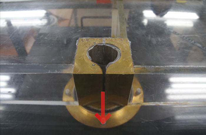
Fig 1: Speaker-driven synthetic jet
A speaker is attached below the device and a jet is emitted from the slot in the direction indicated by the arrow. Click to enlarge.
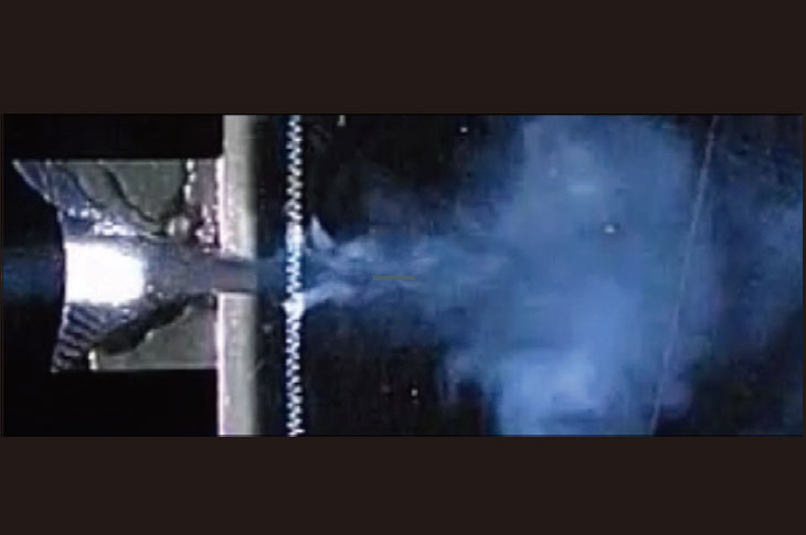
Fig 2: Smoke-wire flow visualization of a synthetic jet.
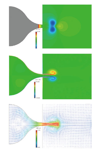
Fig 3: Numerical analysis example of a synthetic jet
Vibrational frequency of 20Hz, slot width 5 mm, characteristic velocity of 3 m/s.
Diagrams of velocity vector (top), pressure distribution (middle), and vorticity distribution (below).
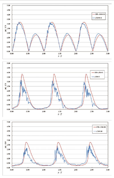
Fig 4: Comparison between experiment and numerical analysis. Similar patterns for velocity fluctuations and amplitude were found.
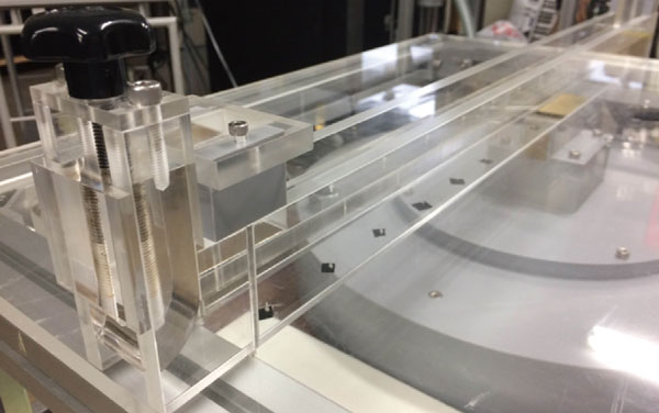
Fig 5: Jet pump using synthetic jet
Experiments and CFD Simulations Using Speaker
One of the essential research activities at Professor Sato’s laboratory is the study of a speaker-driven synthetic jet (Fig 1). A speaker is attached below the device, and oscillating flow is generated at a 5-mm-wide slot. Fig 2 shows the visualization using smoke, and Fig 3 shows the results from an SC/Tetra CFD analysis. Fig 4 shows a comparison between the experiments and the CFD simulations for the velocity measured at various distances from the outlet. As can be seen, the results from the CFD simulation agree well with the experimental results.
Professor Sato’s laboratory also aims to control flow direction by changing frequencies. Controlling the direction of the flow just by changing frequencies would enable the device to be made even smaller. Professor Sato explains that SC/Tetra is used in this research as well, along with experiments.
To Achieve Indirect Contact Between Fluid and Operating Machine
Professor Sato’s laboratory is also investigating how to make a synthetic jet work like a pump (Fig 5). When a typical pump transfers fluids, a vane wheel is directly in contact with the fluids. The effect of bearing oil must be considered if the fluid being transferred is either a chemical or food. When transferring fluids like these, a synthetic jet will be more appropriate. Although the efficiency may not be as high, the synthetic jet ensures complete isolation of the moving parts and the working fluid. Professor Sato says that they are trying to identify the ideal vibrational conditions for optimal fluid transfer.
Synthetic Jet Used for Capsule Endoscope
One possible target application of a synthetic jet is a capsule endoscope. The capsule endoscope is self-propelled and adjusts its orientation by itself. Most mainstream research focuses on a non-contact tail-fin method for orienting the device, where the fin moves by varying the external magnetic force. Professor Sato’s Laboratory is investigating whether a synthetic jet can replace this method.
Synthetic jets are used in vehicles, where the drag force needs to be minimized. Flow that separates from the vehicle body contributes to the drag force. A jet can be used to promote flow attachment on the vehicle body and shift the flow separation point rearwards.
Before synthetic jet research was recognized fifteen years ago, synthetic jets were confused with flow acoustics. The applications for synthetic jets have great potential because of their unique characteristics.
Unexpected Results from an Analysis of an Axial Fan
Professor Sato’s laboratory also investigates flow characteristics of axial fans. A general-purpose fan, which is often used in electronics, is normally developed assuming ideal design conditions. Professor Sato thought “why shouldn’t a fan perform better in an unfavorable environment,” and decided to start investigations.
In fact, fans are rarely exposed to ideal conditions. In computers, fans are often lined up along a wall side by side altering and restricting air flow, and fan filters are seldom replaced. Using a general-purpose fan has a cost advantage compared to designing a special fan for a particular application. In some cases, such as fans used in vehicle air-conditioning systems, specially designed fans are still needed. But the trend toward using general-purpose fans, when possible, is growing. When general-purpose fans are used, useful design information would include the minimum allowable distance from obstacles and quantification of performance degradation due to the presence of obstacles.
As his axial fan research progressed, Professor Sato found that unexpected vibrations occurred under certain operating conditions. Professor Sato also encountered other phenomena he was unfamiliar with, such as improved flow characteristics when an obstacle was located at the outlet or flow reversal when an obstacle was allocated at the inlet.
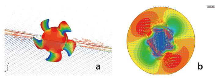
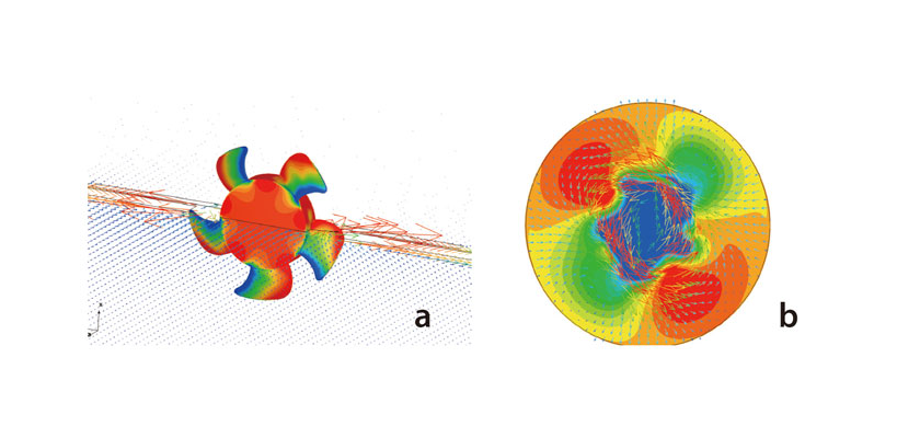
Fig 6: (a) Surface pressure distribution on the blades and velocity vector diagram on the middle cross section of the fan, with a spherical obstacle 320 mm in diameter located 5 mm from the fan. (b) Surface pressure distribution on the obstacle, and velocity vector diagram at the mid position between fan and the obstacle.
Fig 6 shows the results of an analysis for conditions when the unexpected vibrations were detected. Fig 6 (a) shows the surface pressure distribution on the blade and the velocity vector diagram at the middle cross section of the fan, which is 130 mm in diameter and rotates at 2,500 rpm. The calculations were based on a hypothetical condition that a spherical obstacle 320 mm in diameter was located 5 mm from the fan. Fig 6 (b) shows the surface pressure distribution on the obstacle, and velocity vector diagram at the mid position between the fan and the obstacle. The pressure distribution indicates a compartmentalized disturbance, where areas with high and low pressures alternately align. The disturbance rotates 0.1 to 0.2 times as fast as circumferential speed of the fan. This unstable flow was first detected in an experiment, and later reproduced in numerical simulations using SC/Tetra. The simulation results verified that the phenomena could occur with other devices as well, and was not caused by vibrations particular to the device used in the experiment. The severity of the phenomena correlates with fan size. Devastating effects, such as overheating the fan bearing, can be caused. For smaller fans, the vibration may result in unnecessary noise and reduced life. Professor Sato continues to conduct axial fan investigations to better understand the mechanism causing the vibrations.
Tool Highly Preferred by Students
Previously, Professor Sato’s laboratory used another computational analysis tool that was difficult to use and incurred costly support fees. This limited the number of users, which hindered students from pursuing research as extensively as they wished. Unsatisfied with the tool at the time, the students identified SC/Tetra and decided to install the software in 2002. They were pleased that SC/Tetra produced accurate analysis results, and they received excellent technical support. With SC/Tetra, the students can now perform analyses as often as necessary and in a short amount of time. As a result the students are more eager to use the tool during their research. Professor Sato considers the students’ opinions when installing tools in the laboratory. If the tool can be easily used, the students will focus more on the research rather than spending time learning how to use the tool. Another benefit of SC/Tetra is its capability to visualize results. This inspires the students’ fascination with fluid dynamics. The students also appreciate the guidance given at seminars and training sessions organized by Software Cradle. Software Cradle also provides guidance on how to use the software in unconventional situations.
Future Challenges: Calculation of Gas-liquid Two-phase Flow and Coupling Analysis
In the future, Professor Sato hopes to explore gas-liquid two-phase flows and coupled analyses between fluids and an elastic body. As an example of a gas-liquid two-phase flow, Professor Sato has been investigating the flow field downstream of a heat pump compressor. He hopes to gain understanding about the separation mechanism for oil mist in refrigerant. Heat pumps, such as those used in air conditioners, use centrifugal force to separate oil from the refrigerant, but the detailed mechanism still remains unexplained. If the physical mechanisms driving oil separation in refrigerants can be understood, this will lead to improved product designs, shortened development cycles and improved product performance.
The high rotational speeds of a heat pump compressor, as high as 10,000 rpm, could result in failures and potentially damaging accidents during operation. A coupled analysis will enable predicting the frequency where the risks of failures and greater accident damage are heightened, so that the equipment can be operated away from the critical frequency.
Kogakuin University
Faculty of Global Engineering, Dept. of Innovative Mechanical Engineering
- Founded: 1949
- Type of university: Private
- Professor: Kotaro Sato (Doctor of Engineering)
- Location: Shinjuku-ku, Tokyo, Japan
- URL: https://www.kogakuin.ac.jp/faculty/technology/1a1.html
*All product and service names mentioned are registered trademarks or trademarks of their respective companies.
*Contents and specifications of products are as of February 1, 2015 and subject to change without notice. We shall not be held liable for any errors in figures and pictures, or any typographical errors.
Download

