
Texas A&M University
CFD and FSI Analyses of an Aircraft Wing Leading Edge Slat with Superelastic Shape Memory Alloy Cove Filler
Researchers at Texas A&M University are conducting CFD (Computational Fluid Dynamics) and FSI (Fluid-Structure Interaction) analyses of an aircraft wing leading edge slat that uses a Slat Cove Filler (SCF), made from a superelastic shape memory alloy, to reduce aeroacoustic noise when the slat is deployed. Grid management challenges were encountered because the compression of the filler can cause mesh elements to go to zero volume. The CFD software needs to handle complex mesh deformations, nonlinear materials, and facilitate the FSI analysis. Initial results show the computational and experimental results compare well.
Minimizing Aircraft Aeroacoustic Noise Near Airports
Texas A&M University is using sophisticated computational methods to investigate material driven solutions that can reduce aeroacoustic noise produced by aircraft airframes.
High noise levels near airports have been linked to human health issues. While many airports were originally located far from high population areas, urban sprawl has caused significant growth near airports. In addition, increasing passenger demand for air travel means more air traffic. These have led to increased concerns about noise produced by aircraft, which can affect health, disrupt communities, and negatively impact the overall environment.
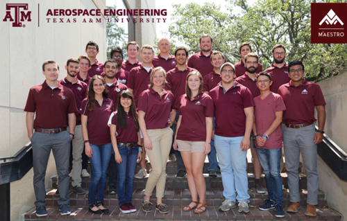 Picture 1: M2AESTRO Research Team
Dr. Darren Hartl, Assistant Professor, Department of Aerospace Engineering at Texas A&M University, leads the Multifunctional Materials and Aerospace Structures Optimization (M2AESTRO) Lab research team that is focused on developing novel structural and material concepts for aerospace applications (Picture 1). The team is comprised of two post-docs, seven graduate students, and a dozen undergraduate researchers. William Scholten, a PhD student and National Science Foundation (NSF) Graduate Fellow, has been performing SCF research since he was an undergraduate researcher.
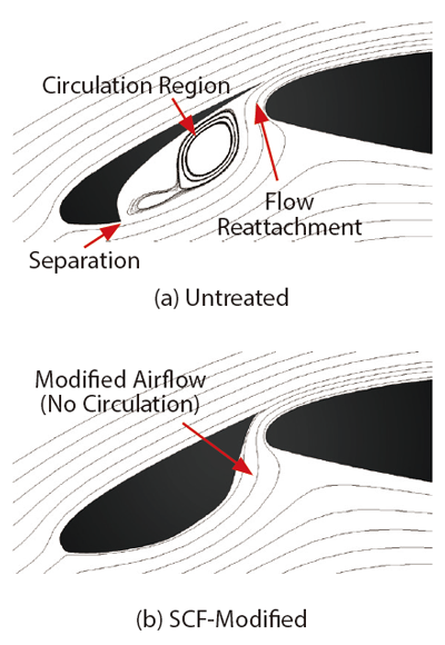
Figure 1: Flow in vicinity of leading–edge slat
Dr. Hartl provides background for one of his team’s projects. “Aeroacoustic noise created by flow passing over an aircraft’s body and wings is one of the major sources of aircraft noise. Traditionally, the airframe is designed to be very streamlined so it is very efficient and produces low noise during cruise conditions (high speed and altitude). Leading-edge devices, such as the leading-edge slat, are flush against the surface of the main wing, significantly reducing drag and noise while allowing for sufficient lift to maintain steady, level flight. However, during approach and landing (low speed and low altitude maneuvers at airports), the slats are deployed to alter the lift and stall characteristics of the aircraft. When deployed, the slats introduce geometric discontinuities to the airflow, which generate airframe noise.” Dr. Hartl notes that a significant source of airframe noise, during approach and landing, is the leading-edge slat due to the circulation region inside the slat-cove (Figure 1a).
Morphing Aerostructure and Large Recoverable Inelastic Deformation
A high potential solution to mitigate the noise produced by the leading-edge slat is the slat-cove filler (SCF) which fills the cove aft of the slat and guides the airflow along a desired path (Figure 1b). The SCF has two main configurations: deployed and retracted (Figure 2). When deployed, the SCF is passively modifying the airflow while maintaining its shape to the aerodynamic loading. When the slat is retracted during cruise conditions, the SCF undergoes significant deformation that would exceed what typical aerospace materials (aluminum, steel, titanium) can sustain before yielding.
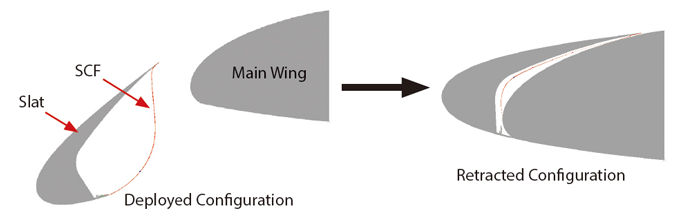
Figure 2: Leading-edge slat configurations
The significant deformation, along with requirements to provide stiffness against the aerodynamic loading and compliance to slat retraction (for reduced actuation force), led National Aeronautics and Space Administration (NASA) engineers to consider superelastic shape memory alloys (SMAs) for the SCF design. Superelastic SMAs are special types of active materials that can undergo a solid-phase transformation under sufficiently applied stress, which enables the material to achieve large amounts of recoverable inelastic deformation.
Dr. Hartl explains the situation when analyzing the aerodynamics of deforming structures. “This thin morphing aerostructure can significantly affect the surrounding flow field. In turn, the flow field can affect the structural response of the SCF. “ The purpose of the research at M2AESTRO is to understand the response of the SMA-based SCF when subjected to flow using a computational Fluid-Structure Interaction (FSI) analysis with Computational Fluid Dynamics (CFD), and experimental wind tunnel tests, to assess its effects on wing performance. This work has been funded by the NSF and the NASA Langley Research Center.
CFD and FSI Make it Possible to Analytically Evaluate the Performance of the SCF at Many Flight Conditions
Using FSI analysis, two-way coupling between the aerodynamic flow field and the SCF structure demonstrated how the SCF behaved when subjected to aerodynamic loads and correspondingly, how these behaviors affected the flow field.
To perform an accurate FSI analysis of the SMA-based SCF, subjected to aerodynamic loading, the M2AESTRO team needed to use a CFD software capable of simulating complex phenomena including significant complex deformation (significant translation and rotation, body-to-body contact, and volume elimination) and nonlinear materials.
Dr. Hartl explains the meshing challenge in this way. “During slat retraction, the SCF undergoes a significant amount of deformation between its deployed and retracted states due to contact with the main wing and the slat. In addition, the SCF is undergoing deformation while connected to a rotating rigid body that is moving relative to a fixed rigid body. The complex deformation of the SCF can quickly lead to the creation of zero volume elements in a typical CFD model.“ Modeling slat/SCF articulation in CFD software is not possible without a feature that can account for complex deformation and near elimination of fluid volumes.
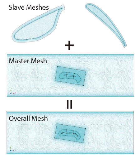
Figure 3: Implementation of overset mesh
SC/Tetra CFD Software Powerful Meshing Capabilities Accommodate Slat Articulation
When the M2AESTRO team was selecting the CFD software to perform the FSI analysis, the ability to handle both the complex deformation of the SCF and the use of nonlinear materials were determining factors. The overset mesh feature in SC/Tetra overlapped movable and deformable slave meshes onto a master mesh. The meshes could accommodate the significant deformation associated with slat articulation. In this work, the research team set the slat/SCF and flap as slave meshes while the tunnel test section and main wing were part of the master mesh (Figure 3).
Coupling SC/Tetra to the structural solver (Abaqus) for the FSI analysis was straight forward because SC/Tetra has a built-in connection to the Abaqus Co-simulation Engine. This was another significant reason for choosing SC/Tetra. In addition, both the fluid and structural solvers were weakly coupled, allowing for the implementation of the SMA constitutive model.
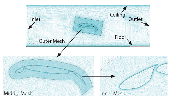 Figure 4: CFD model for Boeing-NASA CRM airfoil
First FSI Analysis of SCF Retraction and Deployment
CFD models of a scaled, 2D section of a high-lift wing, known as the Boeing-NASA Common Research Model (CRM), were developed for retracted, untreated deployed, and SCF-modified deployed configurations at multiple angles of attack. Boundary conditions included walls representing the test section floor and ceiling, surface of the airfoil, zero static pressure at the outlet, and uniform freestream velocity at the inlet (Figure 4). A CFD analysis was performed for each model under the same inflow conditions to investigate how the lift, drag and pressure changed based on the angle and configuration.
Using the overset mesh feature and the SC/Tetra native link to Abaqus, the FSI analysis was conducted for the CRM wing with an SMA-based SCF. Of particular interest was the SCF response to two loading conditions with flow: 1) fixed, fully deployed configuration and 2) slat retraction/deployment. For both load cases, an initial CFD analysis was used to initialize the flow. Based on the FSI analysis the SCF demonstrated under flow, that it could maintain its shape when fully deployed (and thus its noise reducing capability), SCF was compliant to articulation of the slat, and autonomously redeployed during slat deployment.
Early in the FSI analysis, when the slat was subject to significant amounts of articulation (and thus fluid volume deformation), portions of the fluid volume mesh associated with the slat/SCF would be essentially eliminated, or greatly reduced in size, leading to zero volume elements. This could cause problems for the analysis. Dr. Hartl talks about how the team solved this problem. “The solution to this problem was to create a remeshing scheme for the slave mesh (essentially local remeshing of the fluid model). At specified times, as the slat articulated, the FSI analysis was stopped and the deformed slave mesh was remeshed. Flow results from the previous analysis were used as initial conditions for the new FSI analysis.” The results mapping feature in SC/Tetra greatly facilitated this operation. Using both the overset mesh and local remeshing, full slat retraction and deployment was possible.
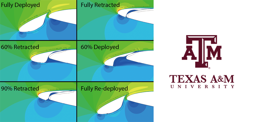
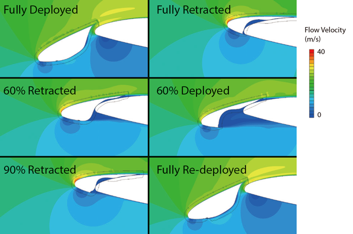 Figure 5: Velocity contours from FSI retraction/deployment analysis
Figure 5 shows the velocity contour of the flow from the FSI analysis at various stages of slat retraction and deployment. The M2AESTRO team believes this is the first FSI analysis of a morphing SMA-based structure attached to a moving rigid body (the slat) relative to a fixed rigid body (the main wing).
Concurrent to the computational work, an experimental model of the CRM wing was developed, constructed, and tested under the same conditions as the computational CFD and FSI models. Both the computational and experimental model results compared well for lift, drag and pressure. This provided an initial means of validating the computational work, and the results have been promising so far.
Currently, techniques for measuring the SCF displacement are being developed. Once implemented, these measures will provide additional data to validate the computational models.
The CFD and FSI analyses permitted assessment of the SCF without the need to build several different experimental test models. The matrix of computational test points was also used to identify safe conditions for future experimental tests. Once validated with experimental data at the safe conditions, the computational analysis can be performed for conditions that may not be possible to attain experimentally. In addition, another virtue of the computational analyses is that significantly more data can be extracted from the computational analysis compared to experimental tests. This is due to geometric constraints and limited (and potentially expensive) metrologies.
Process Turn-Around Time Still a Challenge
While CFD is known to be widely used in the aerospace industry, the time required to generate the computer model and perform the computational analysis can still be an issue. As a result, CFD is often used in the later stages of the aerospace system design process. Dr. Hartl expounds: “During the earlier stages of the design process, engineers typically rely on fast, low-fidelity solutions, such as the panel-method or lifting-line theory. Morphing structures are also becoming more popular in the aerospace industry. Proper analysis of system behaviors when using these complex materials requires multiple CFD analyses for the different configurations that the structure can exhibit. If an FSI analysis is needed for the morphing application, the CFD software must be capable of being coupled with a structural analysis software to facilitate the analysis process.”
Future Computational Needs
The M2AESTRO team will continue to use CFD as a high fidelity method to help grow their understanding about how morphing structures behave in flow. Experimental tests are limited by the number of configurations and conditions that can be tested. CFD can be used to examine many more cases. The pressure distributions from the CFD analysis can also be applied to structural models of a physical prototype to determine how the complex non-linear structures behave under flow. The opportunities are endless, and the M2AESTRO team hopes to continue working with Software Cradle and its products. As Software Cradle continues to enhance FSI capabilities, this will help the M2AESTRO team achieve its goals.
Texas A&M University
- Established: 1876
- Type: Land-grant, sea-grant, space-grant university
- Location: College Station, Texas, USA
- Academic Staff: 4,900
- Students: 68,825 (as of Fall 2017)
- Graduate Students: 15,135 (as of Fall 2017)
- URL: www.tamu.edu
*All product and service names mentioned are registered trademarks or trademarks of their respective companies.
*Contents and specifications of products are as of January 30, 2018 and subject to change without notice. We shall not be held liable for any errors in figures and pictures, or any typographical errors.
Download

