
ACR Co., Ltd
- Applying CFD (Computational Fluid Dynamics) to improve the efficiency of turbochargers for extended-range electric vehicles (EREVs)
- Streamlining production using 3D metal printing
ACR has proficient technical capabilities in vehicle exhaust catalytic converters. They are currently developing micro diesel engines for EREVs (extended-range electric vehicles). Software Cradle’s SC/Tetra CFD software plays an important role in the micro engine development process.
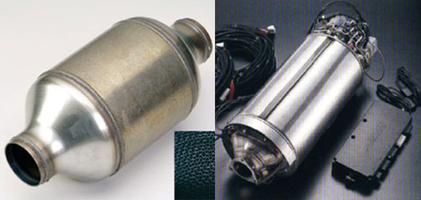
ACR has high technical capabilities in developing emission control devices for trucks and other diesel powered vehicles. PM (particulate matter) emission control devices for diesel engines can be categorized in two ways. DPF (diesel particulate filter) literally burns the collected PM. In contrast, oxidation catalysts, such as platinum, can be used to remove the PM using oxidation reactions. ACR PMR is a PM control device for vehicles, which meets regulation standards for eight regions in Japan. ACR also produces ACR-EXCAT, a catalytic PM control device, for vehicles that produce low PM levels (Fig 1). ACR NXPR, is a NOx and PM control device, that is a very popular product.
While ACR traditionally manufactures a variety of catalytic equipment, honeycombs, and filters, they also manufacture the ACR-NHBL52 which is a portable home power source that is designed to lower peak power usage and provide back-up power in emergency conditions. Equipped with a broad range of skills and tools, ACR conducts evaluations for their own products, and also offers evaluation services for other companies as well.
ACR's most recent interests involve development of small engines to extend EV (electric vehicle) range. Mr. Keiji Kishishita, the Executive Engineer at ACR (Picture 1), manages the overall EREV project on developing auxiliary engines and turbocharger systems.
 Picture 1: Mr. Keiji Kishishita, Executive Engineer, ACR
Better Software and Technical Support: ACR Revisits CFD
Despite rising demand, environmentally friendly EVs are not capable of traveling long distances compared to traditional internal combustion (IC) powered vehicles. However, EREVs can be made to travel farther by using an auxiliary engine for power generation. By using an auxiliary engine to power a generator that recharges the EV batteries, range is extended by making normal stops at the fueling station. With an EREV system, power to the driving wheels is always supplied by the electric motor. This is how the EREV is fundamentally different from the PHEVs (plug-in hybrid electric vehicles). In PHEVs, both the IC engine and the electric motor can be used to power the vehicle. This makes PHEVs more complicated, costly, and not strictly an EV in the purest sense.
ACR uses a single cylinder design for the EREV engine generator for light weight and to maintain low costs. The demand for EREVs is especially high for delivery firms, where fuel consumption is high due to heavy cargo and substantial stop and go driving. In addition, delivery vehicles travel long distances. Delivery vehicles must be in service as much as possible so drivers can use their time efficiently. Delivery firms cannot realistically convert to an all EV fleet because the fleet would be largely unavailable when the EV batteries are being charged. This is an ideal application where auxiliary engine power generator in EREVs can be useful. An EREV delivery fleet would encourage further uses of EVs in the transportation sector.
ACR's EREV development project is sponsored by the NEDO (New Energy and Industrial Technology Development Organization) in Japan. The success of this three-year test program has proved that auxiliary engine EV technology has great potential in promoting increased EV usage. ACR hopes to implement the engine in EREVs in three years (Fig 2).
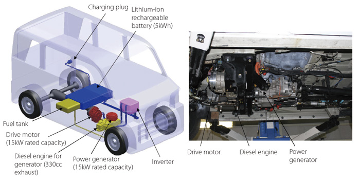 Fig 2: Components of an EV micro diesel power generator
Developing a small auxiliary engine for EREVs presents significant design challenges. These include the pulsation caused by large loads. Also power limitations caused by using low displacement engines prompted ACR to investigate turbocharging to increase engine power. During this time, ACR introduced a thermal fluid analysis tool to help them develop a new turbocharger. Mr. Hiroshi Matsuoka, ACR CEO and President, suggested using computational simulation as a design tool because of growing confidence in the simulation tools which had largely improved in recent years.
Mr. Kishishita and his team initially used a CFD tool developed by a foreign company, but did not implement the tool into their design process, because it was too difficult to operate. Mr. Matsuoka suggested using software with strong local support which would enable them to resolve problems quickly. They selected SC/Tetra.
Designing Efficient Turbocharger
Mr. Kishishita's team is developing a turbocharger that will be much more efficient than the world’s smallest turbochargers found in Japanese Kei minicars. ACR turbochargers will use only about one third the flow rate of typical Kei minicar turbochargers. (Fig 3 and 4). ACR engineers used SC/Tetra to identify the optimal geometry of the turbocharger rotor vane. The optimal design produced a desirable outflow angle for high efficiency. Approximately 6 million mesh elements were used in the computer model (Fig 5). The analysis results showed that the turbocharger efficiency increased as the outflow angle was reduced. Outflow loss was minimized by making the outflow angle extremely small. This minimized friction losses and conversion of energy into heat, thereby improving efficiency (Fig 6). The SC/Tetra analysis results also suggested that by using a very small outflow angle, the efficiency could be 10% better than other products available in the marketplace.
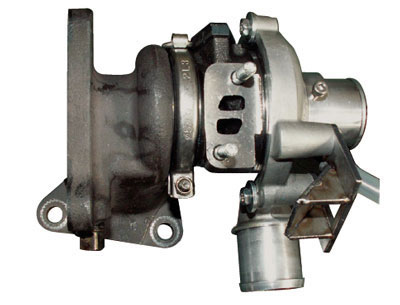
Fig 3: EREV turbocharger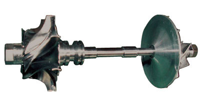
Fig 4: Turbocharger turbine
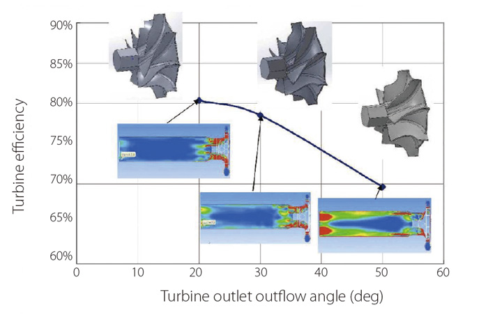 Fig 5: Evaluation of turbocharger vane geometry using simulations
Results show that reducing the turbine rotor vane outflow angle reduces the generation of heat around the rotor vane outlet and improves performance.
The turbine angles are 50, 30, and 20 degrees from right. Contour diagrams of friction heat are shown below
"In the past manufacturers could not implement a design feature such as a very small outflow angle geometry because fabricating this kind of feature was very labor intensive. Manufacturers could not justify the reduced manufacturing productivity and increased cost compared to the performance improvement,” says Mr. Kishishita. ACR solved this problem by introducing metal 3D printing to accurately represent the complicated turbocharger geometry. 3D printing is much more efficient compared to creating complex mold shapes for the traditional casting process. ACR believes they can increase production rates by using more printers which would enable them to achieve cost effective mass production rates for the improved turbocharger.
Validation testing showed that the analysis and test results qualitatively agreed. While ACR engineers plan to improve the accuracy of the analysis results even more, Mr. Kishishita is pleased with the current trends. He believes the simulations can replace physical prototyping and testing which will significantly reduce development time and cost.
Improving the accuracy of the simulations will take time and will possibly lead to larger, more complex models which will also take more time to run. This could hinder ACR engineers from simultaneously evaluating several different geometries. To address this, Mr. Kishishita created an in-house tool that performs a first order calculation for gas flow rate and efficiency, based on rotation speed and pressure. These first order calculations help identify the effects of inlet/outlet area, inlet/outlet vane angle, and flow path outer wall taper. Mr. Kishishita builds upon the results from these first order calculations to perform detailed CFD analyses.
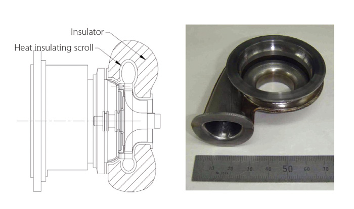
Fig 6: Turbocharger improvement
The turbine scroll was made thinner and wrapped with heat insulator in an effort to increase turbine power.
One of Mr. Kishishita's other design objectives is to make the turbocharger scroll thinner. As the gas enters and leaves the scroll, heat is lost to the outside environment by thermal conduction. The amount of heat loss depends on the position of the scroll. ACR minimizes further heat loss by making the scroll thinner and wrapping it with heat insulating material to reduce thermal conductivity. The impact of doing this is thought to be similar to increasing the turbine efficiency. ACR engineers will evaluate this further using CFD simulations.
ACR also uses thermal fluid simulations to design and develop catalytic devices. They used simulation to assess the mixer design for new catalysts and materials. This analysis involves chemical reactions that occur inside the mixer as the contents are being mixed. Simulation is used to optimize the mixing speed.
ACR engineers have also designed, developed and produced much of the small engine test equipment in-house. This includes test apparatus for fuel jet systems, measuring tools to assess eddies created inside cylinders, and special test equipment for turbochargers. In addition to this, ACR has even developed manufacturing process and machinery for producing nozzles. They developed their own processing techniques, and were able to produce a new fuel jet system in less time and for a lower cost without using dedicated manufacturing suppliers.
While turbocharger development is new to ACR, Mr. Kishishita had significant experience from previous job. He claims that, at one time, adding a turbocharger to a diesel engine was thought to decrease reliability. Yet as the company faced the need to improve fuel efficiency, they were compelled to develop the turbocharger, and Mr. Kishishita was assigned to the project. He says his previous experiences help him with the current work.
Despite Mr. Kishishita’s experience, ACR, as a company, was completely new to engine development. Mr. Kishishita's previous engine experience was with cast iron block diesel engines, whereas the cylinder block for the current project is made of aluminum. The aluminum block was not as rigid as Mr. Kishishita had initially hoped. In addition, developing the fuel injection equipment and other engine components and systems has made the project challenging.
High Operability as Expected
Before Mr. Kishishita and his team started using SC/Tetra they used another tool “that required working with an excessive number of parameters,” as Mr. Kishishita recalls. They had trouble using the tool and never mastered it. They tried to simulate equipment with existing test data so the models could be validated. But the simulation and test results did not match with each other. From this experience Mr. Kishishita started collecting and compiling simulation and analysis data and realized the importance of obtaining strong technical support. When he first learned of the company’s plan to use SC/Tetra, Mr. Kishishita was reluctant. “But our executive CEO and President assured me that the tool has progressed over the years. He also convinced me that we could contact Software Cradle and ask them to help us resolve any problems that may arise. We decided to use SC/Tetra and in the end, the executive decision was right. I find the software ideal for meeting our objectives in many situations,” explains Mr. Kishishita with delight.
Using CFD simulations is also helping ACR reduce cost. Although an experimental data point for a turbocharger test can be acquired in about 5 minutes, the prototype for the test costs roughly 20,000 USD (2.5 million JPY). Lost-wax casting for making the prototype molds is costly and time-consuming as well. Even if a CNC machine is used for making the prototype the cost would still be 1,000 USD or more (100,000 to 200,000 JPY) and take two-weeks to generate model data. ACR engineers found out that they could represent geometries more accurately by installing metal 3D printers. Adding more machines would enable them to mass produce in bulk. Although they need to apply shot peening to make the coarse surface smooth, they managed to set plans for now onward.
Analyzing an EV as a Whole
Thermal management is vital for EVs. A regular internal combustion powered vehicle mainly consists of two heat sources: an engine and a radiator. An EV consists of a motor, inverter, batteries, and many other components that need to be cooled. ACR engineers will use SC/Tetra to evaluate the cooling system components. A motor inverter may be small, but releases heat in kilowatts. ACR engineers will identify the operating requirements that ensure sufficient heat absorption under various driving conditions, such as outside conditions and engine speed and load.
ACR has begun the challenge of developing EV components. SC/Tetra is expected to play an important role.
ACR Co. Ltd.
- Established: 2004
- Businesses: Development and manufacturing of vehicle exhaust filter, Consultation services for diesel engine exhaust treatment devices
- Head Office: Yamato-shi, Kanagawa, Japan
- URL: http://www.acr-ltd.jp/
*All product and service names mentioned are registered trademarks or trademarks of their respective companies.
*Contents and specifications of products are as of January 1, 2015 and subject to change without notice. We shall not be held liable for any errors in figures and pictures, or any typographical errors.
Download

