
Basic Course on Turbulence and Turbulent Flow Modeling 19: 19.1 Analysis of a flow around the main wing of an airplane
Analysis of a flow around the main wing of an airplane
19.1 Analysis of a flow around the main wing of an airplane
In this column, we will see an example of a calculation for the effect of a winglet on the main wing of an airplane. Winglet is a small wing attached to the tip of a main wing as shown in Figure 19.1. The attachment of a winglet is said to improve the fuel efficiency and performance of the airplane. Nowadays, the percentage of the airplanes with winglets is rising, and many of you might have seen those airplanes in action.
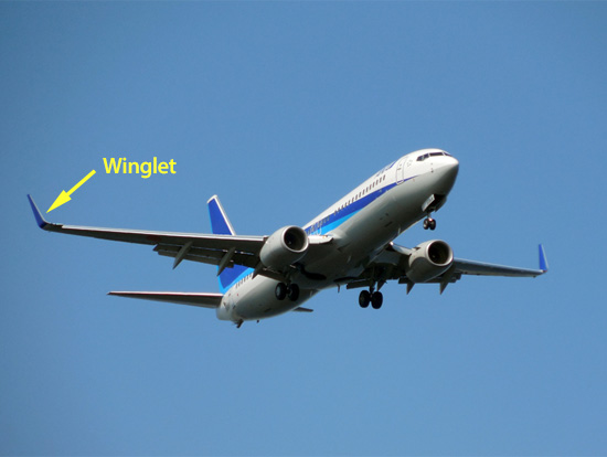
Figure 19.1: Winglet
They say that the effect of a winglet is to control the wingtip vortex. As shown in Figure 19.2, a wingtip vortex is a vortex generated by the air underneath the main wing going around to the top due to the pressure difference at the tip of the main wing. The generation of a large vortex leads to an excessive consumption of energy. Controlling it will improve the fuel efficiency. Airplanes with wingtips are said to have a few percent better fuel efficiency than those without. A few percent amounts to a huge difference in a long-distance international flight. In some cases, winglets are installed additionally after the wing has been manufactured.
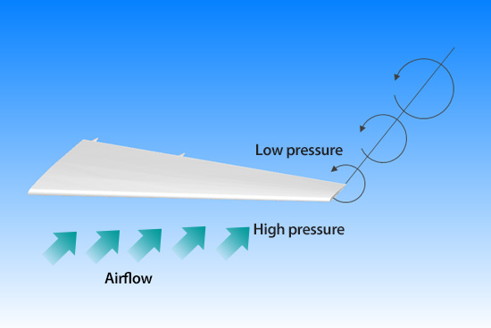
Figure 19.2: Wingtip vortex
Figure 19.3 shows an analysis model. One side of a main wing is placed in the cuboid computational domain. Air flows in from the front to simulate the flight. This time, we set the inflow velocity of 300 km/h. With an angle of attack (five degrees), a takeoff or landing situation is assumed. The calculations are performed with LES using Smagorinsky model. To highlight the effect of the winglet, we run the calculations with two types of main wing: with and without winglet as shown in Figure 19.4.
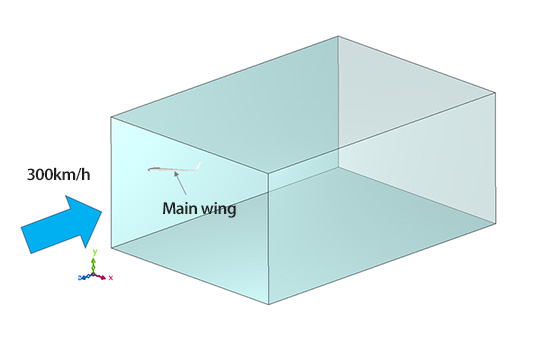
Figure 19.3: Analysis model
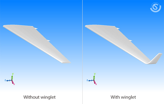
Figure 19.4: Main wing model
Figure 19.5 shows the wingtip vortex in each case. The vortex (in red) is visualized by the second invariant of velocity gradient tensor (refer to Chapter 13, 13.2 ). Compared to the case without winglet, the vortex in the case with winglet is short (weak) and it is generated at the top end of the winglet.
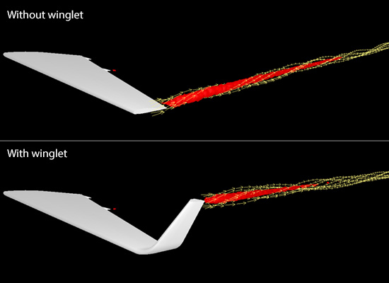
Figure 19.5: Wingtip vortex
How about the change in lift and drag forces with the winglet? As we compare the lift and drag forces on the main wing in the two cases, we find that the lift force is up by 10% while the drag force is down by 7%. Now let us explore why from the analysis results. Figure 19.6 shows the pressure distribution on the bottom surface of the main wing. The lift force is generated due to the pressure difference between the top and bottom surfaces of the wing, but in the case without winglet, the pressure on the bottom surface drops by the generation of the wingtip vortex, and we can see that the lift force is weak near the wingtip. Although a similar effect occurs at the tip of the winglet in the case with winglet, the affected area is small. Moreover, because the orientation of the wing is almost vertical, we can say that its influence on the lift force is small. In sum, the installation of the winglet prevents the reduction of the lift force at the wingtip, thereby yielding the increase in the total lift force.
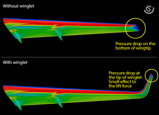
Figure 19.6: Pressure distribution on the bottom surface of the wing
Next, let us look into the drag force. As shown in Figure 19.7, there are pressure drops in the case without winglet on the top surface of the wing toward the back. This is probably caused by the wingtip vortex. Since this portion of the surface is leaning toward the downstream, pressure drop on this portion leads to an increase in the drag force. Although similar pressure drops can be found in the case with winglet on the top surface of the wing toward the back, the affected area is small. We can say that its influence on the drag force is small compared to the case without winglet. As a result, the drag force in the case with winglet becomes smaller.
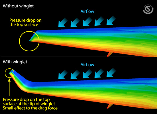
Figure 19.7: Pressure distribution on the top surface of the wing
Lastly, I would like to show you an animation of the wingtip vortex (Figure 19.8). We can see the air flowing from the front curls counter-clockwise just around the wingtip.
Figure 19.8: Animation of the wingtip vortex (above: without winglet, below: with winglet)
19.2: Closing remarks
This chapter is the last of the “Basic Course on Turbulence and Turbulent Flow Modeling” 19-chapter series. I hope the contents have been as friendly as I tried them to be. Although turbulent flows are complicated phenomena, we can say the mechanisms that govern them are not special among fluid phenomena by the thought of the same governing equations (Navier-Stokes equations) for both laminar and turbulent flows. In addition, I can speak with a deep feeling that we could reproduce such a characteristic vortex phenomenon as the wingtip vortex in this column by solving Navier-Stokes equations. Thank you so much for reading through this series of columns, and I will be delighted if it becomes valuable to you.

About the Author
Takao Itami | Born in July 1973, Kanagawa, Japan
The author had conducted researches on numerical analyses of turbulence in college. After working as a design engineer for a railway rolling stock manufacturer, he took the doctor of engineering degree from Tokyo Institute of Technology (Graduate School of Science and Engineering) through researching compressible turbulent flow and Large-Eddy Simulation. He works as a consulting engineer at Software Cradle solving various customer problems with his extensive experience.

