
Basic Course on Turbulence and Turbulent Flow Modeling 13: 13.1 Analysis of a flow around a cylinder, 13.2 Calculation results of LES, 13.3 Comparison with RANS
Methods of turbulent flow calculation (7) Calculation example of LES
13.1: Analysis of a flow around a cylinder
We covered the overview of LES in the previous column. We will discuss a specific example of calculation in this column. The example is a flow around a cylinder; we introduced an animation in Chapter 5 Mechanism of turbulent flow (2). Analysis of a flow around a cylinder is a flow calculation where a cylinder is placed in a uniform flow as shown in Figure 13.1. When the flow goes past the cylinder, it generates famous ‘Karman’s vortices’. Depending on velocity, type of fluid (density and viscosity), and the diameter of the cylinder, however, sometimes Karman’s vortices are not generated. In some other times, vortex structures are formed with more complexity than Karman’s vortices. The calculation example introduced here is a very high-Reynolds-number flow around a cylinder with Reynolds number of ten million based on the diameter of the cylinder and the flow velocity. Highly complex vortex structures are formed around the cylinder. The condition with Reynolds number of ten million corresponds to a flow around a bullet train traveling at 200 km/hr.
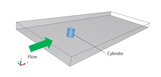
Figure 13.1: Calculation of flow around a cylinder
13.2: Calculation results of LES
Figure 13.2 shows vortex tubes for the flow around the cylinder calculated with LES, which is visualized by means of the second invariant of velocity gradient tensor.
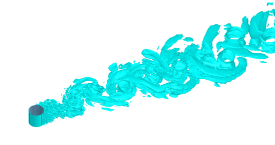
Figure 13.2: Calculation result of a flow around a cylinder (LES)
The second invariant of velocity gradient tensor is given by:
(Magnitude of vorticity – Magnitude of shear)
If we draw the region where this index has a positive value, namely where vorticity is stronger than shear, we can visualize vortex tubes as shown in Figure 13.2. In this calculation, we can see a lot of fine vortex tubes in the region behind the cylinder. We can also see that the vortex tubes gradually grow larger as they move downstream, and they also meander widely. This appears to be an overlap of small vortex tubes and Karman’s vortices as an overall movement.
Incidentally, Karman’s vortices are vortex tubes that are generated parallel to a cylinder, or perpendicular to the flow; however, a close look at the vortex tubes in Figure 13.2 reveals that there are vortex tubes generated in such directions as different from Karman’s vortices (Figure 13.3). These are called ‘longitudinal vortices’, and they are the vortices generated when turbulence motions are enlivened. It is said that more and more complex vortex structures are formed when vortex tubes of different orientations interfere with each other.
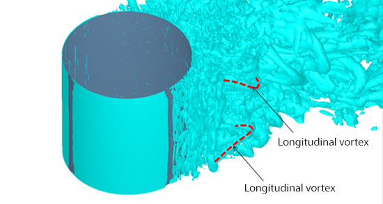
Figure 13.3: Close view near the cylinder (LES)
Evidently, if we can prepare a proper mesh for LES, we can capture this kind of highly complex motions of vortex tubes. People say that in human society, a group will get enlivened with an addition of a slightly different personality. I find it interesting that turbulent flows and human society share this similar mechanism.
13.3: Comparison with RANS
Figure 13.4 shows the calculation result for a flow around a cylinder using RANS, with the same mesh and conditions as in LES. SST k-ω model is used as the turbulence model. You may notice the utter difference in the appearance of vortex tubes, in comparison to Figure 13.2. In the RANS calculation, only the thick vortices parallel to the cylinder are generated. Neither longitudinal vortices nor fine vortex tubes can be seen. Moreover, the vortex tubes do not meander; they move almost in a straight line. We can presume that this is because with RANS model, no matter how fine we arrange mesh, generation of highly transient vortex tubes on the cylinder surface cannot be predicted, which in turn hinders the subsequent development of complex vortex structures.
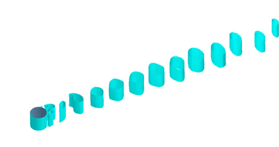
Figure 13.4: Calculation result of a flow around a cylinder (RANS)
Figure 13.5 shows a comparison of eddy viscosity between LES and RANS. For both LES and RANS, we can see regions of large eddy viscosity around vortex tubes. In RANS, however, the predicted values of eddy viscosity are quite large compared to those in LES. Generation of fine vortex tubes is hindered likely because of this large eddy viscosity. In the next column, we will discuss ‘Hybrid model’ which combines LES and RANS.
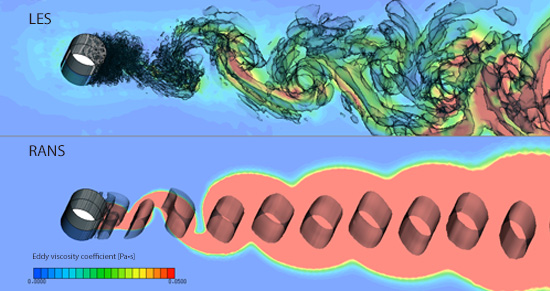
Figure 13.5: Comparison of eddy viscosity distribution

About the Author
Takao Itami | Born in July 1973, Kanagawa, Japan
The author had conducted researches on numerical analyses of turbulence in college. After working as a design engineer for a railway rolling stock manufacturer, he took the doctor of engineering degree from Tokyo Institute of Technology (Graduate School of Science and Engineering) through researching compressible turbulent flow and Large-Eddy Simulation. He works as a consulting engineer at Software Cradle solving various customer problems with his extensive experience.

