
Case Study – Learn about Thermo-Fluid Analyses Optimization No. 12: Design of a model airplane - Optimal cross sectional shape of a wing (1)
Design of a model airplane
- Optimal cross sectional shape of a wing (1)
From this column, let us see an example of exploring the optimal cross sectional shape of a wing and of a propeller by using EOopti and SC/Tetra in the design of a model airplane. We will explain the following topics in this column and the succeeding two columns; Lift force coefficient / drag force coefficient, Joukowski airfoil drawing, model creation, and the result of optimal solution exploration.
Lift force coefficient / drag force coefficient
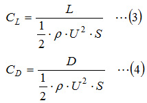
As shown in Figure 1.1, regarding forces acting on an object in a fluid, the force component perpendicular to the relative velocity of the fluid and the object is called drag force and the force component parallel to that is called lift force. Lift force L [N] and drag force D [N] are expressed with the following equations.
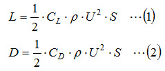
where,
CL : Lift force coefficient
CD : Drag force coefficient
ρ: Fluid density [kg/m3 ]
U: Relative velocity of the fluid and the wing [m/s]
S: Area of the wing [m2 ]
The area of a wing is obtained for the product of chord length and wingspan shown in Figure 1.2. Both lift force and drag force are proportional to the area of the wing and to the square of the relative velocity of the fluid and the wing; therefore, the optimal cross sectional shape of a wing will be the shape with the largest lift force coefficient and the smallest drag force coefficient.
Lift force coefficient and drag force coefficient are derived from the following equations using lift force and drag force obtained by a wind tunnel experiment or a CFD analysis.
SC/Tetra outputs pressure components acting vertically on an object surface and shear force acting horizontally on an object surface. Among these components, the sum of the components perpendicular to the flow is lift force, and the sum of the components parallel to the flow is drag force.
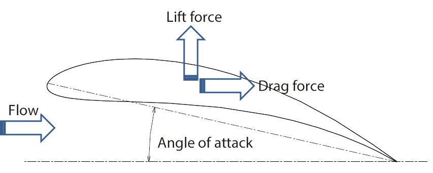
Figure 1.1 Lift force and drag force
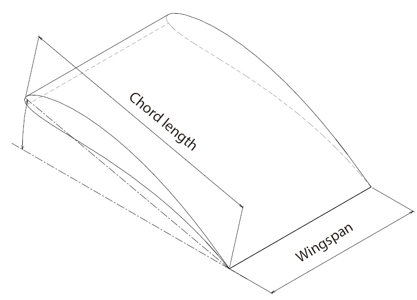
Figure 1.2 Chord length and wingspan
Various cross sectional shapes of a wing with a large lift force coefficient and a small drag coefficient have been examined by conducting wind tunnel experiments and such. They are provided as a database, as shown in Figure 1.3, using angle of attack as a variable. For the design of a wing, generally airfoil databases are used; however, we will conduct a computational wind tunnel experiment using SC/Tetra to obtain the lift force and drag force of an arbitrary cross sectional shape of a wing. Then, we will explore the shape with the largest lift force coefficient and the smallest drag force coefficient by using EOopti.
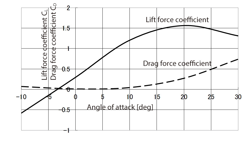
Figure 1.3 Variation of lift force coefficient and drag force coefficient along with angle of attack
We will use Joukowski airfoil that can define the cross sectional shape using two variables, among various airfoils ever proposed, to create a model and analyze it simply. Joukowski airfoil is a shape that a unit circle on the complex plane ξ-η shown in Figure 1.4 has been converted to the shape on X-Y plane shown in Figure 1.5 by the following equations. Changing the center position of the circle on the ξ-η plane will vary thickness and camber of the cross sectional shape.
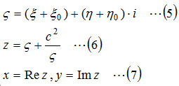
Note that ReZ and ImZ respectively represent the real number and the imaginary number of Z. Here, c is ξ value of the intersection between the circle and ξ axis shown in Figure 1.4. It can be obtained from the center coordinates of the circle (ξ0,η0) by the equation 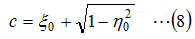 .
.
Figure 1.6 shows Joukowski airfoils with different combinations of ξ0 and η0. When ξ0 is larger, the airfoil thickness increases, and when η0 is larger, the airfoil camber becomes more curved.
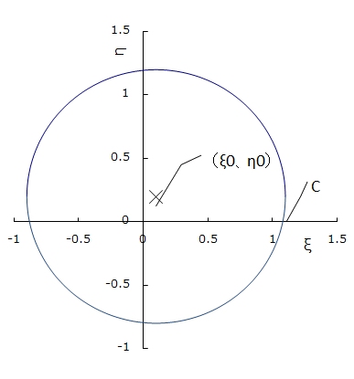
Figure 1.4 Circle on ξ-η plane
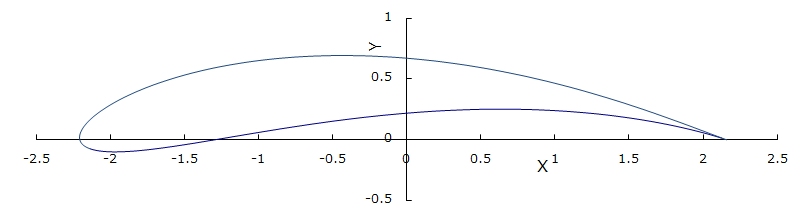
Figure 1.5 Mapping onto X-Y plane by Joukowski conversion
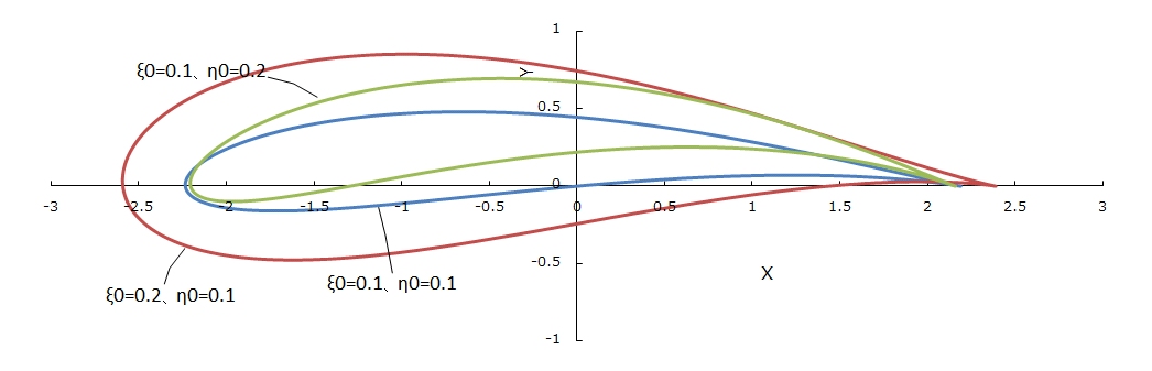
Figure 1.6 Shape variation with different combination of ξ0 and η0
The next column will describe how to create a model.
[Reference] Kikaikougaku binran ‘Ryutai kougaku’ (Mechanical engineering handbook, ‘Fluid engineering’),
User's Guide Optimization (Option)

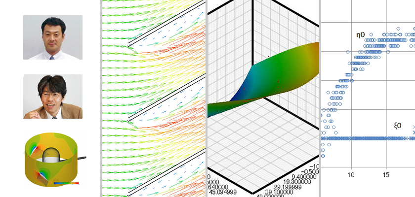
About the Author
Professor Gaku Minorikawa | Faculty of Science and Engineering,
Department of Mechanical Engineering, Hosei University
Certified environmental measurer (noise and vibration)
- 1992 Joined EBARA CORPORATION
- 1999 Became an assistant at Hosei University Faculty of Engineering
- 2001 Obtained Doctor of Engineering at Tokyo Institute of Technology
- 2004 Became Assistant Professor at Hosei University Faculty of Engineering
- 2010 Became Professor at Hosei University Faculty of Science and Engineering

About the Author
Takahiro Ito | Senior Researcher, ORIENTAL MOTOR Co., Ltd.
- 1982 Graduated University of Tsukuba (College of Engineering Sciences) and joined Nippon Steel Corporation, where he worked on the development of heating and cooling facilities.
- 1988 Joined ORIENTAL MOTOR Co., Ltd. and worked on the design and development of ventilator vanes and frames.
- 2008 Obtained Doctor of Engineering at Hosei University.
- He is Senior Researcher of ORIENTAL MOTOR Co., Ltd. (as of January 2014).

