
Case Study – Learn about Thermo-Fluid Analyses Optimization No. 11: Optimal shape of a louver (3)
Optimal shape of a louver (3)
For the optimal design of a louver, we explore a condition which provides the minimum loss coefficient and length per pitch using the length and angle of the louver as the design variables. This column will describe the result of the optimal solution exploration by EOopti.
In the Optimal shape of a louver (1), we saw that length per pitch is determined by only angle from the relation among pitch, length, and angle of a louver. Let us see the response surface to examine how loss coefficient can be determined. Figure 3.1 is the response surface of loss coefficient and shows that loss coefficient on the vertical axis hardly varies even if length L changes. That is, loss coefficient also depends on only angle.
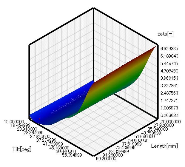
Figure 3.1 Response surface of loss coefficient ζ
Figure 3.2 shows the optimal solution distribution. Both length per pitch and loss coefficient depend on only angle. Figure 3.3 shows the variations of length per pitch and loss coefficient depending on angle. Figure 3.2 and 3.3 show that loss coefficient does not decrease so much when length per pitch exceeds two and angle decreases. In contrast, loss coefficient extremely increases when length per pitch goes below 1.5 and angle increases. The relation between length per pitch and loss coefficient is a tradeoff; therefore, the optimal louver angle depends on which has the priority between loss coefficient and the cost and size of the louver. Note that there is a range of angle providing high tradeoff effect. Figure 3.3 shows the optimal range is from 30 to 40 degrees.
We can say that length of a louver does not affect loss coefficient, except extreme cases of several millimeters or hundred millimeters, so it can be set arbitrarily. In addition, the louver angle affects loss coefficient and length per pitch, and the optimal angle range is from 30 to 40 degrees.
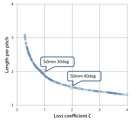
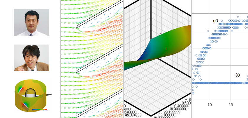
Figure 3.2 Optimal solution distribution
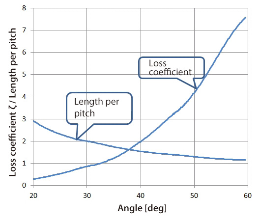
Figure 3.3 Variation of loss coefficient ζ and length per pitch along with louver angle
Figure 3.4 and 3.5 show the velocity distribution and pressure distribution, respectively, around louvers of angle 30 degree. Figure 3.6 and 3.7 show those of louvers of angle 40 degrees. Let us compare Figure 3.4 and 3.6. When the angle is 40 degrees, the flow separation area is larger and the velocity between louvers is faster than when the angle is 30 degrees. In addition, Figure 3.5 and 3.7 show that when the angle is 40 degrees, the area around the louver tip where flow impinges and pressure becomes high and the flow separation area where pressure is low are both wider than when the angle is 30 degrees.
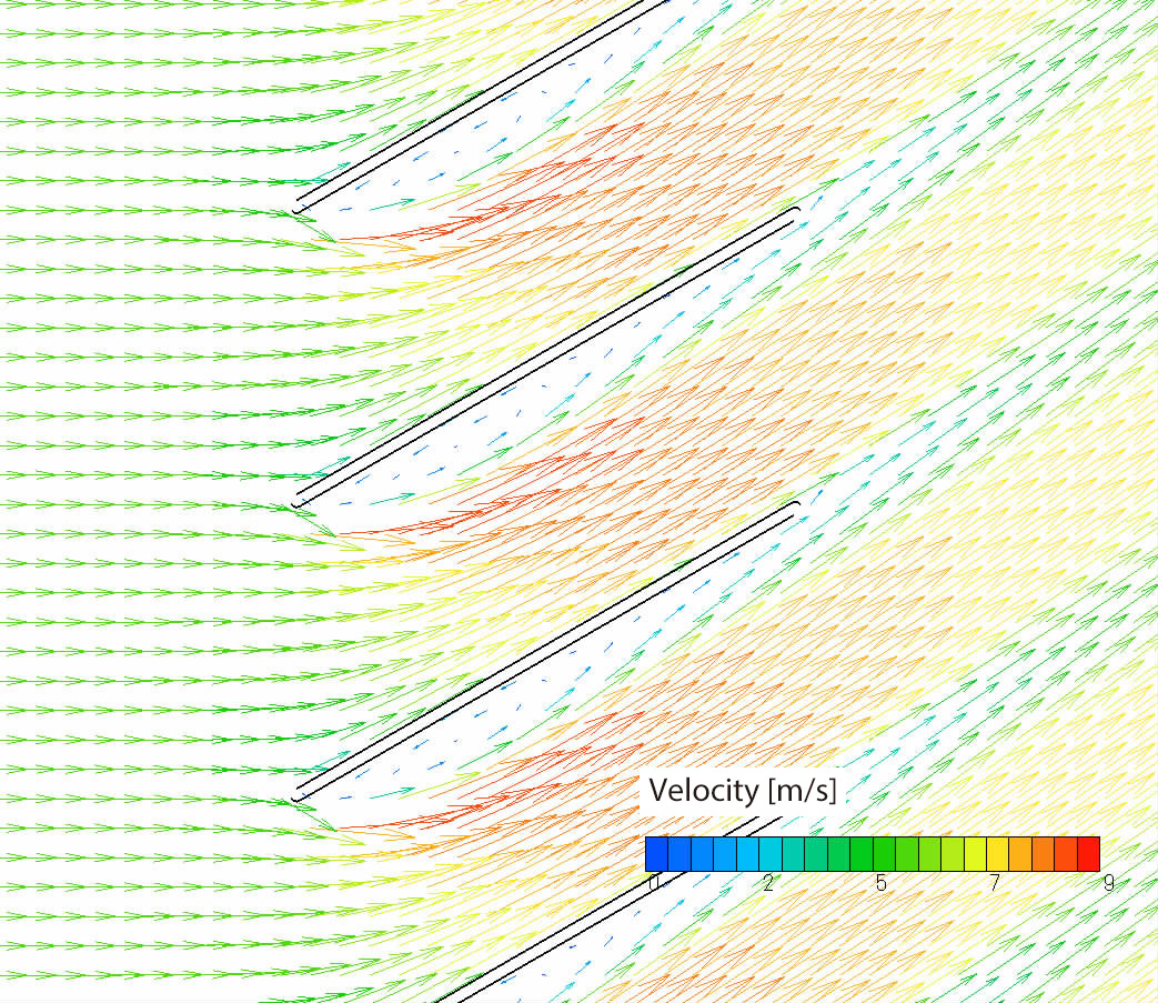
Figure 3.4 Velocity distribution when louver length is 50 mm and its angle is 30 degrees
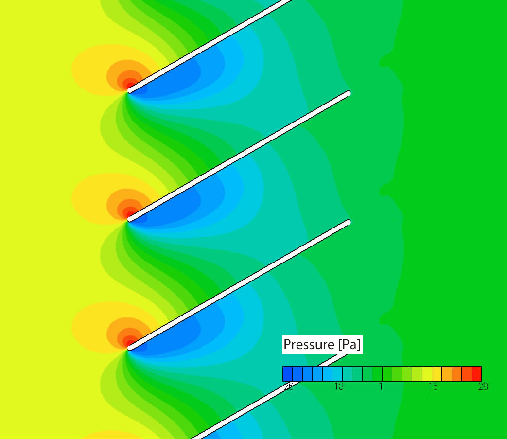
Figure 3.5 Pressure distribution when louver length is 50 mm and its angle is 30 degrees
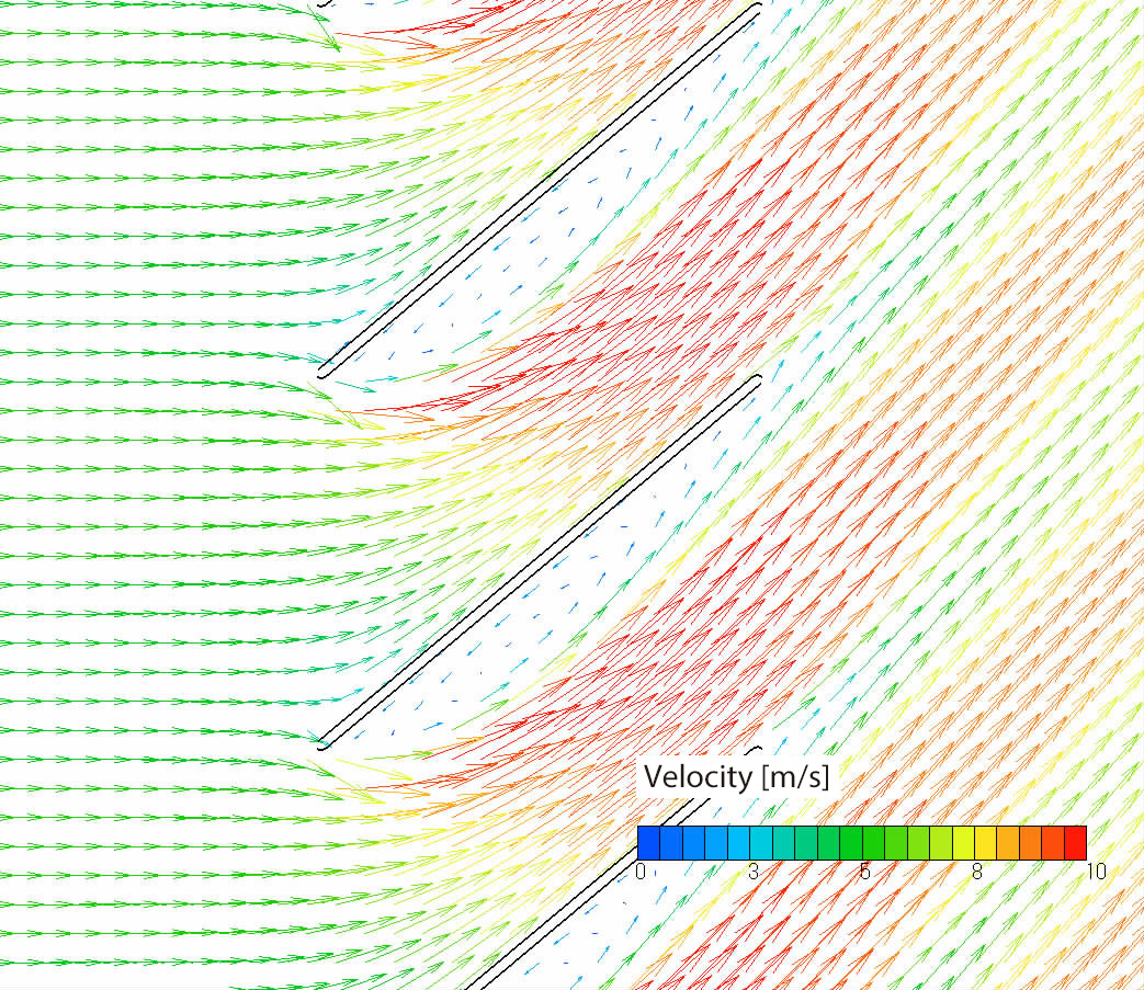
Figure 3.6 Velocity distribution when louver length is 50 mm and its angle is 40 degrees
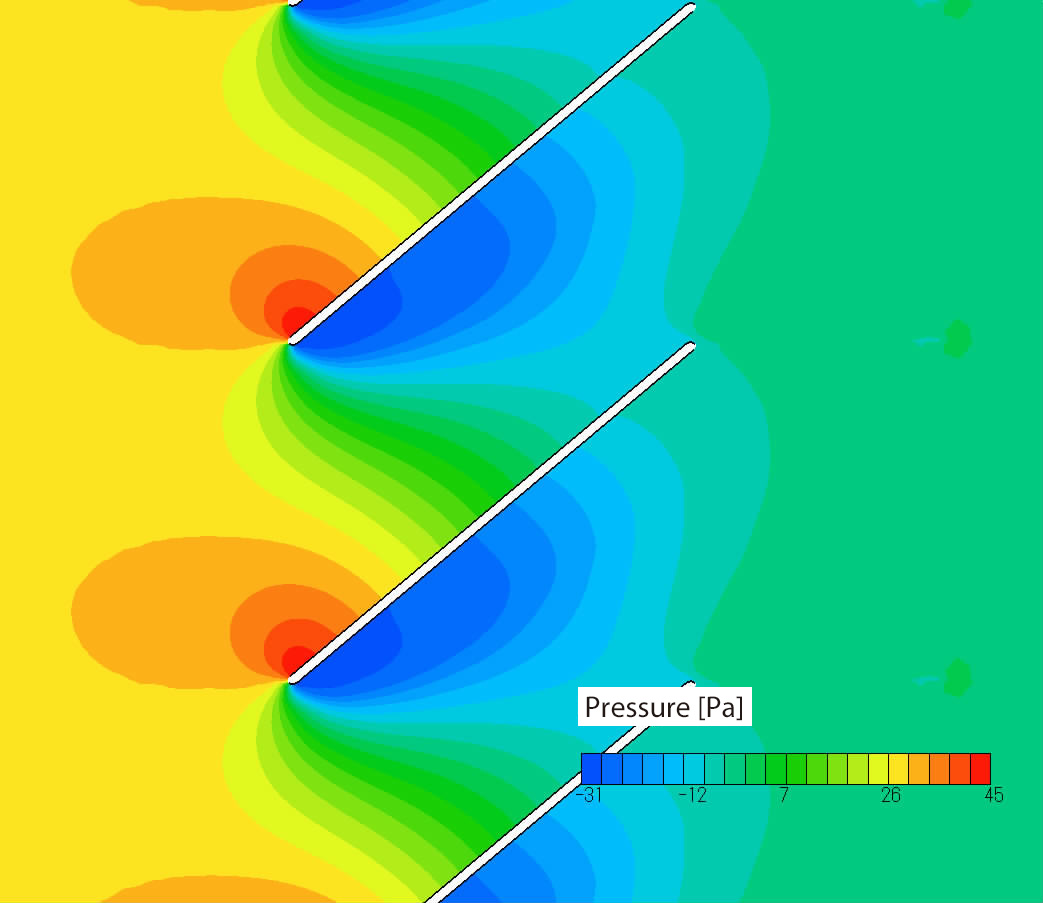
Figure 3.7 Pressure distribution when louver length is 50 mm and its angle is 40 degrees
In the next column, we will design a wing of a model airplane by using EOopti and SC/Tetra.
[Reference] Kikaikougaku binran ‘Ryutai kougaku’ (Mechanical engineering handbook, ‘Fluid engineering’),
User's Guide Optimization (Option)

About the Author
Professor Gaku Minorikawa | Faculty of Science and Engineering,
Department of Mechanical Engineering, Hosei University
Certified environmental measurer (noise and vibration)
- 1992 Joined EBARA CORPORATION
- 1999 Became an assistant at Hosei University Faculty of Engineering
- 2001 Obtained Doctor of Engineering at Tokyo Institute of Technology
- 2004 Became Assistant Professor at Hosei University Faculty of Engineering
- 2010 Became Professor at Hosei University Faculty of Science and Engineering

About the Author
Takahiro Ito | Senior Researcher, ORIENTAL MOTOR Co., Ltd.
- 1982 Graduated University of Tsukuba (College of Engineering Sciences) and joined Nippon Steel Corporation, where he worked on the development of heating and cooling facilities.
- 1988 Joined ORIENTAL MOTOR Co., Ltd. and worked on the design and development of ventilator vanes and frames.
- 2008 Obtained Doctor of Engineering at Hosei University.
- He is Senior Researcher of ORIENTAL MOTOR Co., Ltd. (as of January 2014).

