
Case Study – Learn about Thermo-Fluid Analyses Optimization No. 10: Optimal shape of a louver (2)
Optimal shape of a louver (2)
For the optimal design for a louver, the previous column explained about pressure loss and the relation among the length, angle, and pitch of the louver. This time, we will create a model and set conditions.
We perform a two-dimensional flow analysis assuming the flow in the louver as two-dimensional. For the height direction, we create a one-pitch model and set periodic boundary conditions because the flow behavior repeats per pitch. In addition, we set a flow path of 1,000 mm before and after the louver. So, the model will be a band-like plate as shown in Figure 2.1. Figure 2.2 is a zoomed part of the louver. Then, we set a stationary wall condition on the portion corresponding to the louver surface, and set a free slip wall condition on other surfaces. For the surfaces shown in the figure with the caption “Periodic boundary condition”, we set periodic boundary conditions so that the number 11 and 12, and the number 21 and 22 will be the pairs, respectively. We set the velocity 5 m/s as the fixed velocity for the inlet, and set 0 Pa as the fixed static pressure for the outlet.

Figure 2.1 CFD model of a louver
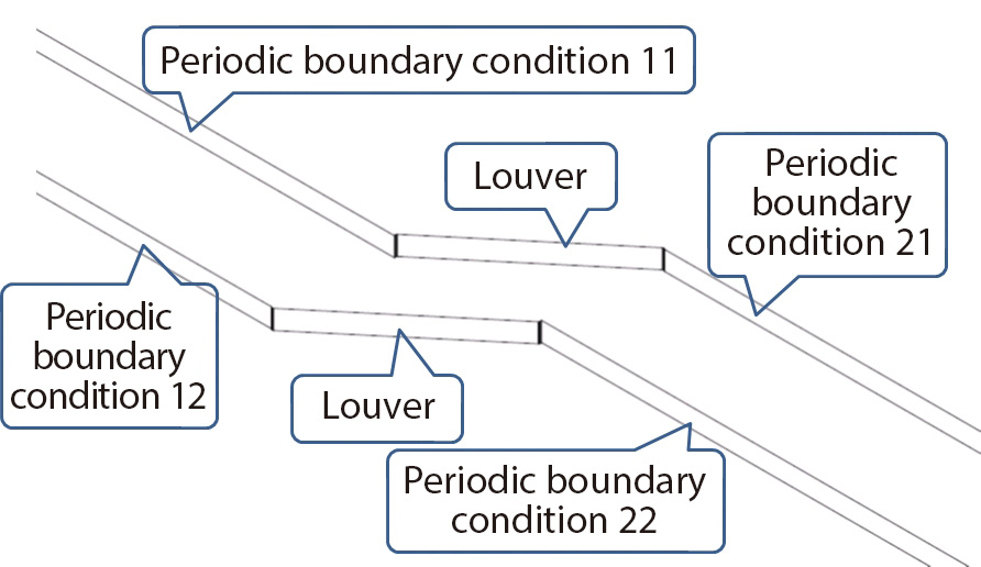
Figure 2.2 Zoomed louver
The number of design variables is two: the length and angle of the louver slat; therefore, the number of samples is defined as (2+1)×(2+2)=12. Here, let us set the parameters in EOopti as shown in Figure 2.2: Louver length 20 – 100 mm, louver angle 15 – 60 degrees.
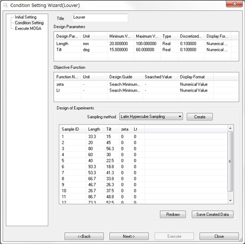
Figure 2.3 Condition setting in EOopti
We prepare design of experiments, create a model based on the planned experimental conditions, and obtain pressure loss using SC/Tetra. Next, we obtain loss coefficient ζ and length per pitch L/t. Here, the length per pitch is 1/sinθ where θ is the louver angle. Loss coefficient ζ is derived by the following equation: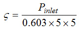
In the equation above, Pinlet is the pressure at the inlet, from the following factors: Density of air 1.206 kg/m3 , inflow velocity 5 m/s.
Figure 2.4 and 2.5 are examples of an analysis result output from SC/Tetra.
Figure 2.4 and 2.5 show velocity distribution and static pressure distribution, respectively, with the condition of 50 mm for the louver length and 30 degrees for the louver angle. The calculation was performed for one pitch; however, the figures show the results for several pitches using the periodic copy function of Postprocessor.
In Figure 2.4, we can see that the flow direction varies along the louver, the flow separates at the edge of the louver, and the velocity increases between the louvers. In Figure 2.5, we can see that, at the edge of the louver, static pressure increases where the flow meets, and decreases where the flow separates. Between the louvers, static pressure decreases as velocity increases, then, static pressure increases. In addition, we can see that static pressure distribution is almost even at the outlet of the louver.
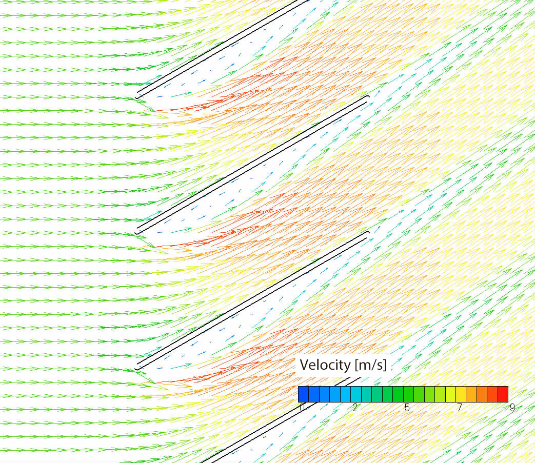
Figure 2.4 Velocity distribution
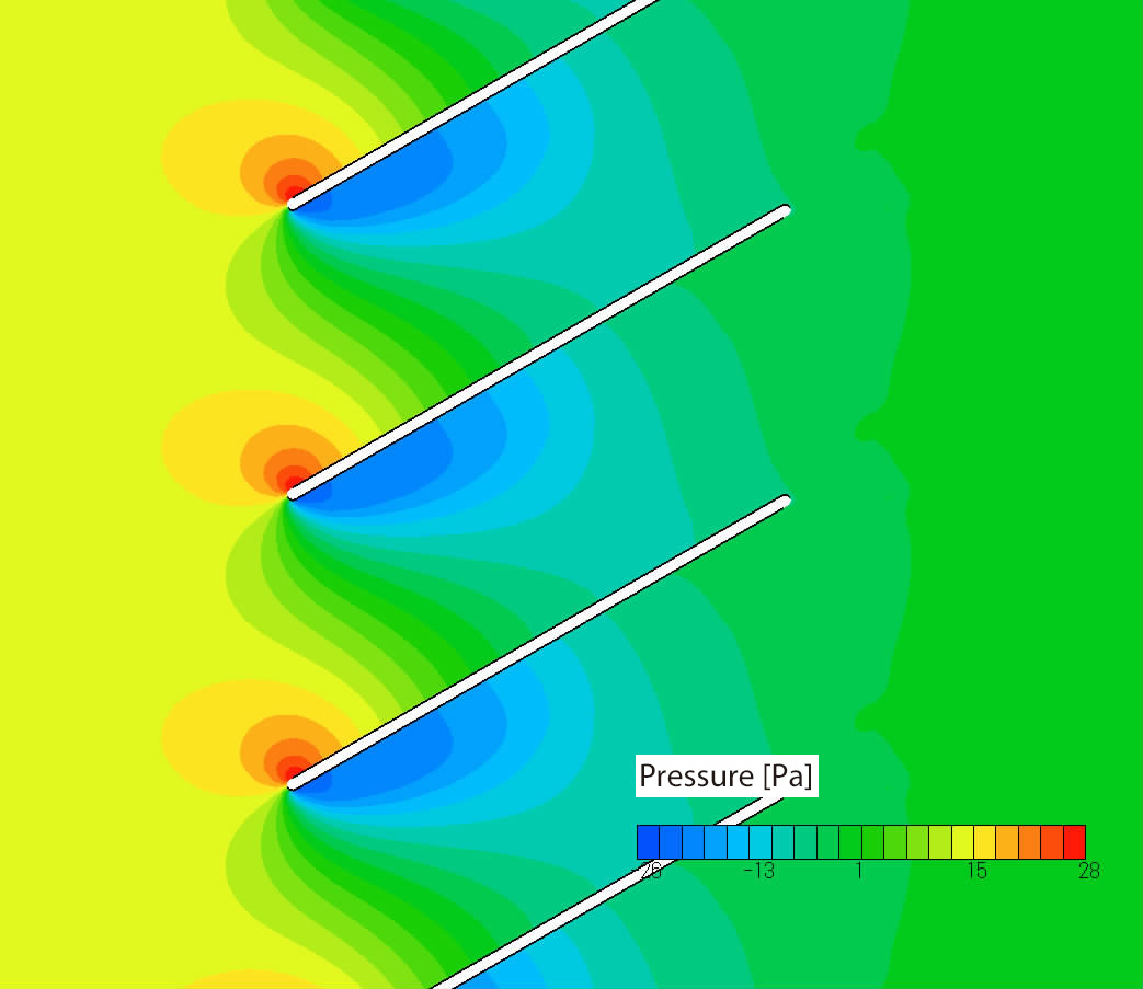
Figure 2.5 Static pressure distribution
In the next column, we will see the exploring results of optimal solution.
[Reference] Machine Engineering Handbook – Fluid engineering (in Japanese)
User's Guide Optimization (Option)

About the Author
Professor Gaku Minorikawa | Faculty of Science and Engineering,
Department of Mechanical Engineering, Hosei University
Certified environmental measurer (noise and vibration)
- 1992 Joined EBARA CORPORATION
- 1999 Became an assistant at Hosei University Faculty of Engineering
- 2001 Obtained Doctor of Engineering at Tokyo Institute of Technology
- 2004 Became Assistant Professor at Hosei University Faculty of Engineering
- 2010 Became Professor at Hosei University Faculty of Science and Engineering

About the Author
Takahiro Ito | Senior Researcher, ORIENTAL MOTOR Co., Ltd.
- 1982 Graduated University of Tsukuba (College of Engineering Sciences) and joined Nippon Steel Corporation, where he worked on the development of heating and cooling facilities.
- 1988 Joined ORIENTAL MOTOR Co., Ltd. and worked on the design and development of ventilator vanes and frames.
- 2008 Obtained Doctor of Engineering at Hosei University.
- He is Senior Researcher of ORIENTAL MOTOR Co., Ltd. (as of January 2014).

