
Keihin Corporation
Performing Aerodynamic Noise Analyses to Meet Demands for Noise Reduction
As EVs and HEVs (hybrid and electric vehicles) become more common, the need for quiet and highly efficient vehicle HVAC (Heating, Ventilation, and Air Conditioning) equipment has become increasingly important. Noise reduction is critical for air-conditioning equipment and tools using fans to move air. Keihin Corporation uses SC/Tetra to conduct aerodynamic noise analyses to identify noise sources and evaluate countermeasures to reduce noise levels. Using computational tools to predict noise is extremely complex and is considered a very challenging flow simulation application.
Keihin Corporation is one of the largest automotive component manufacturers in the world. Their business entails research and development (R&D), design, and manufacturing of engine, transmission, air-conditioning and electrical control units for motorcycles, automobile, motorsports, and general-purpose machine.
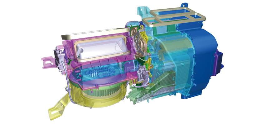
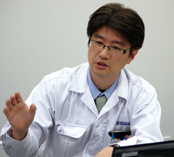
Mr. Junya Washiashi – Engineer (pic 1), and Mr. Jun Onodera - Assistant Engineer (pic 2) from Keihin’s Air-conditioning System Development Department, Air-conditioning System Business Operations, conduct R&D on HVAC unit of automobile air-conditioning systems. An automobile air-conditioning system consists of an HVAC unit, a compressor and condenser. The function of HVAC unit is generation of warm or cool air, to maintain comfortable temperature and humidity of car cabin, and to defrost a windshield, the main components of HVAC unit (a heat exchanger unit that heats/cools the air to the desired temperature as in fig 3), and a blower unit that moves the air into the vehicle.
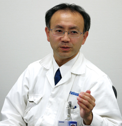
Left: Mr. Junya Washiashi, Engineer, Air-conditioning System Development Department, Air-conditioning System Business Operations (Pic 1)
Right: Mr. Jun Onodera, Assistant Engineer, Air-conditioning System Development Department, Division 1, Air-conditioning System Business Operations (Pic 2)
Higher Demand for Quiet Vehicle Environment due to the Emerging Eco-friendly Cars
As effective air-conditioning system is crucial to create a comfortable space for passengers, customer expectations are high. When climate controlled vehicles debuted, passengers were satisfied just having an air-conditioning system. But today’s customers expect low noise and vibration from the HVAC system, as well as the elimination of the odors, pollen dusts, and small particulate matter (PM2.5). The emergence of EVs and HEVs has increased the demands placed on the HVAC system. These eco-friendly cars are quiet most of the time, and generate engine noise only when necessary. This makes noise from other sources more noticeable, especially if it is not generated from the engine. As a result, the demand from vehicle manufacturers for HVAC noise reduction increases each year.
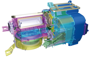 Fig 3 The structure of an HVAC unit, consisting of the blower unit (the cylindrical part - lower left) and the heater unit
CAE has become more important to us because prototyping is costly. CAE allows us to evaluate device capability and determine where the noise may occur before prototyping,” says Mr. Washiashi. Filters are used to block fine particles such as pollen dusts and PM2.5, but the air flow rate requirement into the vehicle must also be maintained while also consuming minimum amount of energy. To design a device that satisfies such a requirement, Keihin engineers are always concerned about the ventilation system resistance, which is quantified as a flow rate index. Simulation is critical for calculating the flow rate index.
Extending the Simulation from the Heater Unit to the Blower Unit
Keihin Corporation has conducted many different kinds of simulations, including fluid flow and aerodynamic noise analyses. They first started using an analysis tool to perform fluid analysis in 1999 to evaluate the flow inside a heater unit. In 2002, they used a specially customized tool to allow their design engineers to more flexibly experiment with simulating the heater unit and the tool was only designed to simulate the flow in the heater unit. In 2003 they started using SC/Tetra to simulate rotating air flow field of the blower with the drive motor.
Keihin Corporation primarily uses SC/Tetra to analyze the air flow inside their blowers. They evaluate different design concepts and modeling techniques with the goal of identifying the best shape. One example is a transient analysis of a rotating body to visualize the air flow, predict the flow rate, and estimate the fluid noise. Recently they have taken more interest in understanding the physics within their blowers. Now they use the analysis tool to both improve blower performance and evaluate the physical phenomena to determine if there are other mechanisms for further improvements.
Keihin Corporation also uses SC/Tetra in the early stages of concept design and development. One of their objectives is to reduce the number of prototypes they must build. They believe that evaluating designs analytically and minimizing prototype production will continue to grow in importance. However, this will be a long-term challenge to achieve.
Another example of how Keihin Corporation uses SC/Tetra in their design is the estimation of the blower PQ (Pressure/Flow) characteristics (fig 4). Blower capability determines the performance of the overall HVAC system, and is critical for the entire design. Keihin engineers used SC/Tetra to identify the PQ characteristics at the operational voltage, based on the relationship between the blade torque calculated from analysis and the torque characteristics of the electric drive motor derived from experiments.
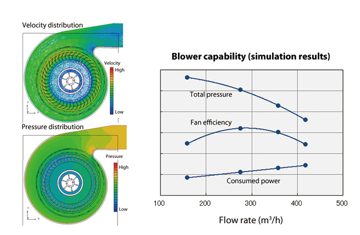 Fig 4 Simulating the blower capability (in terms of PQ characteristics)
Conducting Frequency Analyses to Identify the Source of Noise
When Keihin Corporation first introduced SC/Tetra, the tool was only used to evaluate the air flow field. Now they have extended its application to aerodynamic noise analyses.
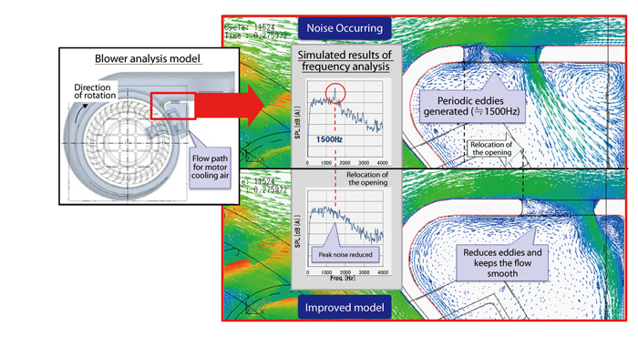 Fig 5 Example of an aerodynamic noise analysis at the opening for the blower motor cooling air flow path: relocating the opening reduced peak noise levels.
Aerodynamic noise analysis requires highly accurate calculations because the sound pressure differences are only a few Pascals at most. LES (large eddy simulation) is used for turbulence modeling on a 48-core machine. Using the aerodynamic noise analyses, Keihin Corporation identified the sound source and improved the geometry of the blower to reduce the noise. The analysis identified the problem emanated from the small air inlet at the bottom of the blower, which is used for cooling the motor. A 1500Hz frequency noise was detected in a prototype test. Keihin Corporation performed analysis to visualize the air flow and found that periodic eddies were generated at the air inlet, as shown in the vector diagram in fig 5. According to the flow analysis, eddies were created 1500 times per second (1500Hz) which agreed with the observations from the experimental tests. Based on the hypothesis that the turbulence eddy formation rate at the cooling air inlet was the primary source of noise, Keihin engineers relocated the air inlet and performed the simulation again. The results showed a more uniform flow, and the disappearance of the previously-detected periodic eddies. The 1500Hz peak frequency no longer existed. Keihin engineers produced a revised prototype that incorporated the improvements from the simulation results, and successfully eliminated the noise.
Fluid analysis has also been used to develop measures to eliminate the noise generated when transferring the air to the heater unit (fig 6). The Heat/Defroster mode in the vehicle air-conditioning system directs conditioned air to the windshield and heated air to the passenger footwell simultaneously. Noise was generated from the small gap between the sliding doors that opened and closed to control the warm air from the heater unit and the cool air from the evaporator. Keihin engineers conducted a fluid analysis to identify the noise source which helped them construct countermeasures.
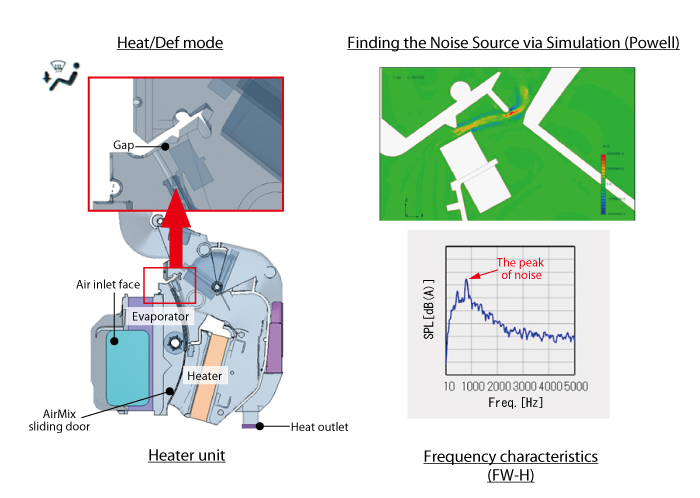 Fig 6 Example of how fluid analysis is used to identify the sound inside the heater unit: noise occurs when air is transferred through the gaps.
Improving the Simulation Environment for Better Analysis
Keihin Corporation aims to provide industry leading hardware and facilities so their design engineers and CFD specialists can learn to use the analysis tools and fully utilize their capabilities. When SC/Tetra was initially introduced Keihin Corporation only had a few CFD specialists. Now the number of specialists has grown to three times greater. Selected engineers specifically work with noise reduction of the overall blower and inner heater unit. Their challenge is to improve and develop the tools, environment, and entire system so more design engineers can easily and flexibly perform the analyses.
Easy Mesh Generation of a Blower is a Key Factor
Keihin engineers found SC/Tetra suitable for meeting their simulation objectives, which were to perform blower transient analysis and conduct aerodynamic noise analysis. However, the primary reason they initially selected SC/Tetra was its ease of preprocessing (geometry preparation and mesh generation). They tried other simulation tools for the early blower simulations, but they were not able to generate boundary layer elements around the vanes, even after reducing the number of vanes to simplify the model. As a result they could not accurately calculate the pressure in the blower. After several unsuccessful attempts to mesh boundary layer elements around the vanes, they tried SC/Tetra. Using SC/Tetra they found that mesh generation, including the boundary layer elements, could be done quickly and effortlessly.
“Another reason we chose SC/Tetra was that it was much faster,” says Mr. Onodera. From previous experience, Keihin engineers were aware that simulating a blower was time-consuming. When they switched to SC/Tetra, analysis time was reduced to one third with the same hardware specifications, and the accuracy of the results did not change.
Separating Each Sound
Several functions were added to SC/Tetra to support Keihin engineers’ pursuit of better aerodynamic noise analysis. In SC/Tetra Version 9, only a compound waveform could be calculated, making it impossible to separate individual sounds. When Mr. Onodera and his engineers asked Software Cradle for additional support, an interim solution was proposed to simulate a compound waveform from various observation points and to estimate a particular sound from the shape differences. SC/Tetra Version 11 has since advanced to where it can separate sound pressures for each sound using a single observation point. As the waveform cannot be separated into individual sounds from experimental data, this analysis function is extremely beneficial for Keihin engineers.
“Not only were they quick to incorporate our requests regarding software functions, but Cradle engineers were also very responsive with their everyday support. This is another benefit that comes with using Cradle software,” comments Mr. Onodera.
Aiming to Evaluate the Overall System through Coupling
Keihin engineers are eager to continue using simulation as a part of the production process. Although their CFD specialists are currently the only ones using SC/Tetra, Keihin Corporation has a longer term goal of making the tool available to more engineers. They want to increase the number of software licenses, prepare manuals to train their engineers to learn the operations, and develop automated tools to facilitate blower fluid analyses. This work has already been initiated as Keihin engineers started using the Cradle Visual Basic Interface to automate calculation processes and have also started receiving Cradle–led training.
Keihin Corporation has expanded the boundaries of CFD to make their design tasks more efficient. SC/Tetra has played a critical role in contributing to Keihin Corporation’s improved product development.
Keihin Corporation
- Founded December: 1956
- Business: Manufacturing of vehicle components
- Representative: Tsuneo Tanai, President and CEO
- Location of Head Office: Shinjuku-ku, Tokyo, Japan
- Capital: Approx. 6.9 billion JPY (as of March 31, 2013)
- URL: www.keihin-corp.co.jp/english/
*All product and service names mentioned are registered trademarks or trademarks of their respective companies.
*Contents and specifications of products are as of April 30, 2011 and subject to change without notice. We shall not be held liable for any errors in figures and pictures, or any typographical errors.
Download

