
OVAL Corporation
Using CFD (Computational Fluid Dynamics) upfront to design better flowmeters
OVAL Corporation is a flowmeter manufacturer, who has cultivated their own advanced technology to develop a diverse range of products. They have started using SC/Tetra to improve product accuracy and quality. In this article, OVAL Corporation explains how they benefit from using CFD and also discusses challenges they experienced when introducing the tool.
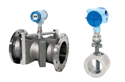 Picture 1: Flowmeter - ultrasonic flowmeter on left, vortex flowmeter on right
OVAL Corporation is a fluid equipment manufacturer that produces many different kinds of fluid flowmeters. The company was founded in 1949 with the mission to manufacture an oval-shaped gear meter, which was first developed by the president of Nissan Motor Company. Since that time, in addition to their three most popular products, oval, Coriolis, and vortex flowmeters, the OVAL Corporation has developed a diverse range of products (Picture 1). As the largest pure-play manufacturer of fluid equipment, they apply highly advanced technology to the design of their products. This enables them to provide optimal flowmeters that satisfy client needs, even those with unique specifications, such as the government.
Flowmeters are used to measure the amount of fluid that passes through a pipe per unit time. They can be found in many aspects of our daily lives. They are used to measure fuel flows at gas stations, residential water flows, process flows at chemical and food plants, waste water flows from a factory, exhaust gas flows, and many others. Flowmeters can be generally categorized as either volume flowmeters or mass flowmeters. A volume flowmeter measures the fluid volume that passes through an area per unit time. A mass flowmeter measures the fluid mass that passes through the area per unit time. Volume flowmeters can be further categorized as actual measurement typed and inferential typed. OVAL Corporation's oval gear flowmeters are actual measurement typed volume flowmeters. A fixed volume of fluid is transferred by each rotation through two sets of oval gears inside the flowmeter. This enables measuring the total flow rate by monitoring the number of rotations. In contrast, OVAL Corporation's ultrasonic and vortex flowmeters, as shown in Picture 1, are inferential typed flowmeters.
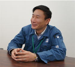
 Picture 2: Mr. Takeshi Motomiya, Assistant Manager, R&D Group 1, R&D Division, OVAL Corporation
CFD Application as a More Practical Approach
OVAL Corporation started thinking about SC/Tetra back in fall 2013. They were not satisfied with the accuracy and processing speed of the fluid analysis software they had been using, although this was the only software they had used since starting their analysis efforts.
Thinking back to just before officially introducing SC/Tetra, Mr. Motomiya (Picture 2) says: “It was good that we could use the trial version for free during the first two months. ” With thorough technical support provided by the Software Cradle staff, OVAL Corporation was able to perform thorough evaluations during the trial period. From this impression, Mr. Motomiya was convinced of the software's feasibility. “We felt that we could use the tool without problems,” says Mr. Motomiya.
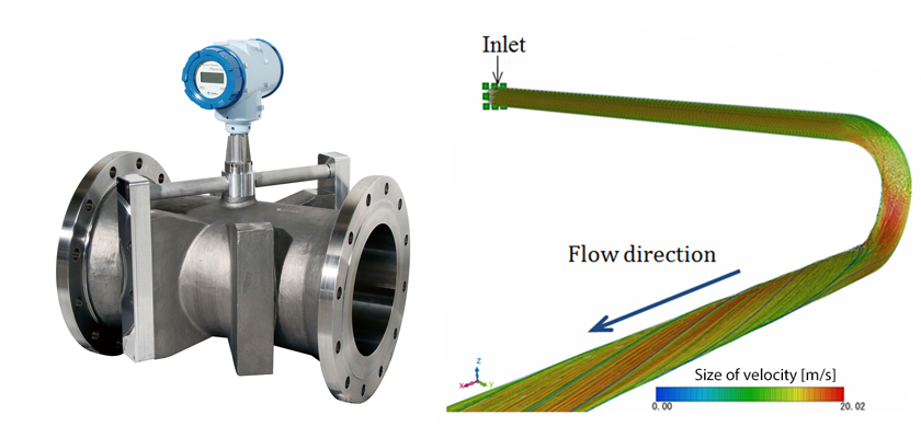
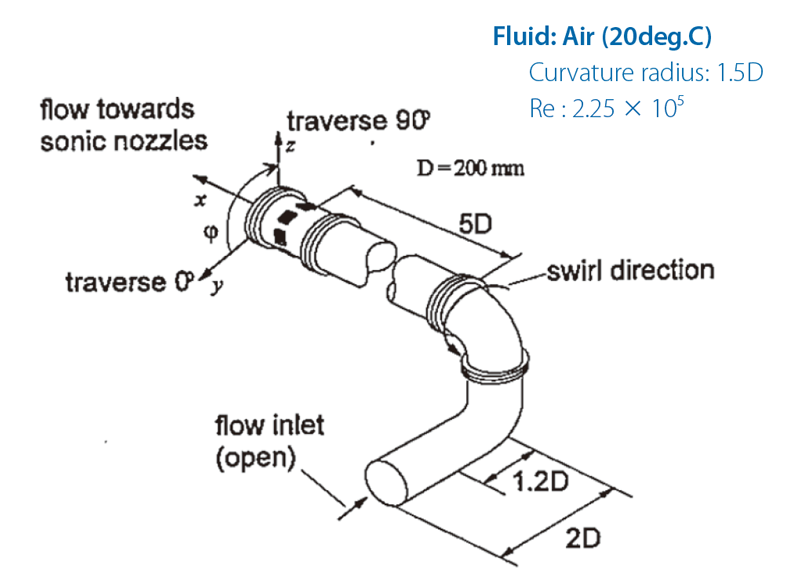 Fig 1: Comparison between velocity distribution near flow inlet and outlet (experiment conditions tested by Hilgenstock et al.*2).
Positive Comparison between Measurement and Analysis Values
After officially introducing SC/Tetra, OVAL Corporation first compared analysis and measurement results for estimation-based flowmeters, which are often used in plants. The measurement accuracy of these flowmeters will be affected by the velocity distribution inside the pipe. In many cases, where components, such as elbows, joints, and valves are located upstream of the flowmeter, swirling flow and drift current can occur, undermining the flowmeter's capability. ISO (International Organization for Standardization)*1 regulations specify that sufficient pipe length must be maintained between the flow components and the flowmeters. In reality, retaining sufficient pipe length is difficult to achieve because of limitations imposed by available space. As a solution, a flow conditioner to help straighten the flow are sometimes used to achieve an ideal velocity distribution using short pipe lengths.
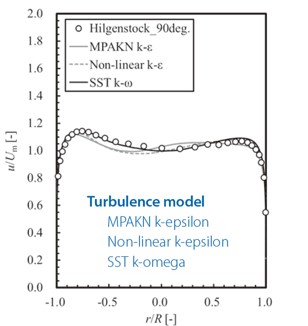 Fig 2: Comparison between analysis and experiment values undertaken by Hilgenstock et al.*2
Results using SST k-ω model were in closest agreement with experiment values.
Figure 1 shows an experiment using double bend pipes. The model was used for PTB (the Physikalisch-Technische Bundesanstalt, Germany's national metrology institute) standards verification. The experimental results show the velocity distribution for a complex piping configuration*2. As shown in Figure 1, the fluid inlet is located at the lower front and the outlet is located at the upper left. A Laser Doppler flowmeter was used to measure the velocity distribution inside the pipe near the outlet.
The comparison in Figure 2 shows the turbulence model that produced the closest agreement between the calculated and measured values. According to this analysis, the SST K-ω model produced the best agreement with the test results. The horizontal axis on the graph shows the distance from the center of the pipe cross section, and the vertical axis shows the velocity distribution on the cross section. Both axes are dimensionless values, which are divided by either the pipe radius or the average velocity at the cross section.
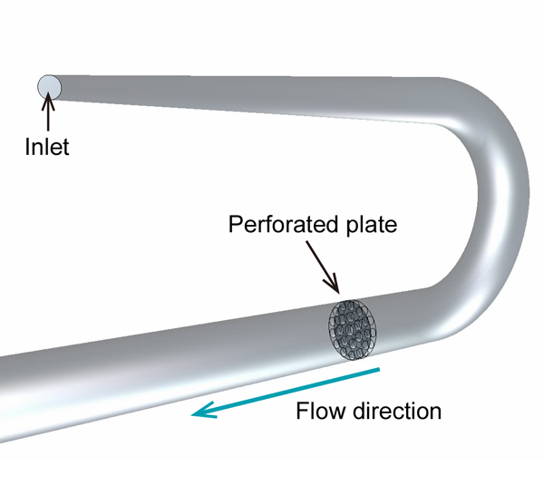 Fig 3: Comparison between velocity distribution between perforated plate and the point where 1.5 times far from pipe radius in downstream (experiment conditions tested by Xiong et al.*4). Fluid flows from rear part towards front.
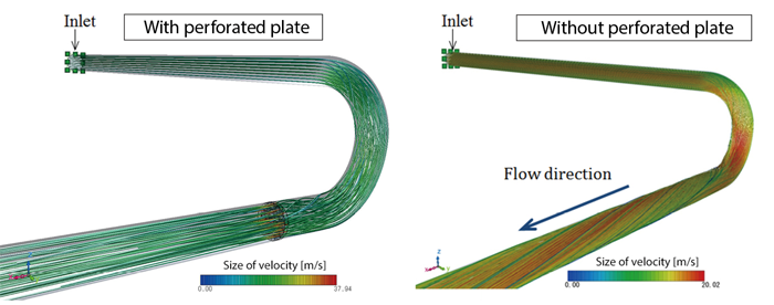 Fig 4: Streamlines shown in the analysis results calculated using SST k-ω model. Swirling flow occurs without perforated plate.
For the next step, OVAL Corporation verified the case where a perforated plate was located downstream of the pipe bend. The geometry is illustrated in Figure 3, where the flow conditioner is called an AKASHI plate*3. Fluid enters through the inlet. In this analysis, the SST K-ω model was used, based on previous analysis results which demonstrated high accuracy using this turbulence model. Figure 4 shows streamlines for the analysis results. Swirling flow occurs when no perforated plate is used. The left diagram in Figure 5 shows the velocity distribution 1.5 pipe radii*4 downstream. The vertical axis shows the distance from the center of the pipe cross section, and the horizontal axis shows the velocity distribution. The difference between the analysis and test results near the wall is likely caused by the influence of the wall on the measurement results. Regardless of which analysis tool is used, the calculated values for the velocity near the wall will be greater than the actual values when the SST k-ω model is used. With all things considered, Dr. Fujikawa (Picture 3) says that the analysis values “are in good agreement with the experiment values, except for the results near the wall.
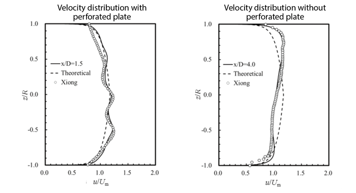 Fig 5: Velocity distribution. Analysis results were in close agreement with experiment when SST k-ω model was used.
 Picture 3: Mr. Toshihide Fujikawa (D.Eng), Assistant Manager, R&D Group 1, R&D Division, OVAL Corporation
Aiming to Front Load the Design Process with Computational Analysis
“Our final goal is to achieve front loading. To do so, the first thing we need to do is to accumulate technical know-how,” says Dr. Fujikawa. OVAL Corporation is planning to use SC/Tetra during the pre-production design phase. This will reduce prototyping and experiments, which will ultimately minimize cost and reduce development time. He explains: “To keep the development cost low, we have to reduce the number of trial-and-error evaluations during prototyping and experiments that involve making and testing actual equipment. This cannot be done without CFD predictions.” Another reason CFD is so important at the OVAL Corporation is that their flowmeter product mix calls for wide varieties but small quantities. Flowmeters must be designed differently to comply with different specifications, including calibers, pressure, temperature, and viscosity. SC/Tetra is a useful tool for narrowing down the many design decisions to identify the best values to meet specific customer requirements. Using CFD will speed up development. Dr. Fujikawa hopes to achieve front loading and improve product accuracy and quality.
OVAL Corporation is currently performing steady-state analyses for about 30 different design studies using models that contain ten to twenty million mesh elements. It takes one to two weeks to calculate a solution in four parallel processes. “There are some things that can only be clarified by performing transient analyses. Although calculation time is a problem that still needs to be resolved, we are considering taking up this challenge,” says Mr. Motomiya. He further explains: “That will mean increasing the degree of parallelism. It would be better if we can run multiple jobs using just one license.” Cloud services, which have become more common in recent years, can be the solution. Using cloud services, several hundred parallel calculations can be processed. Cloud services provide significant benefits for a user who does not regularly process large scale calculations. Mr. Motomiya also recognizes the possibilities and advantages that could come from using cloud services. He will try using these services if the benefits exceed the costs.
SC/Tetra's Fast Mesh Generation Function is a Great Advantage
Regarding the support provided by Software Cradle, Dr. Fujikawa says: “Their engineers are not only quick but extremely helpful. They are our reliable partners.” As a Japanese firm, Software Cradle provides manuals and related documentation in Japanese as well as English. This helped OVAL Corporation engineers who are not familiar with English.
While using SC/Tetra, what struck Dr. Fujikawa the most was the integral capabilities of the SC/Tetra Postprocessor. For example, the data needed to produce the graph shown in Figure 2 was obtained from the analysis results. When an analyst wants to generate the velocity distribution of an arbitrary cross section according to the existing experiment data, the analyst can simply select the spot on the window without having to input coordinates.
OVAL Corporation also finds mesh generation easy using SC/Tetra. The CFD software they used previously did not have the automatic mesh generation function. This forced them to use a step-by-step procedure just to generate meshes. They ended up using another CAE (Computer Aided Engineering) tool, which was compatible with the CFD software, to generate mesh elements. They had to use a multi-step process to change the file extension, export the data, and finally import the data into the CFD software. “SC/Tetra is very easy to use. It generates the mesh automatically. We can adjust settings separately to generate mesh elements even around walls too,” says Dr. Fujikawa. The improved capabilities reduce processing speed and provide a substantial advantage to OVAL Corporation.
No One-Click Answer is Possible
To truly improve the flowmeter design/development processes, CFD must be used effectively. To do so, Dr. Fujikawa explains that they first determine the required performance and then consider possible design options. Unrealistic options are deleted by theoretical calculations. The remaining options are evaluated using CFD to identify the best options. Dr. Fujikawa explains that this will ultimately reduce the number of experiments.
OVAL Corporation is intent on using CFD to help achieve their design objectives; however, they also know they must use the most feasible approach. Their approach is based on recognizing that “CFD is not a magic tool.” It does not produce results with just one click of a button. “It is crucial that engineers are sufficiently trained when using the tool,” says Dr. Fujikawa. Engineers can decide whether or not the calculated results are correct when they have substantial knowledge not only in the operation of the CFD tool, but also in academics, such as fluid engineering and CFD analysis. “Even if engineers are well-trained, once they stop using the software regularly, there is little hope for attaining optimal results. It won’t change even if the software has amazing capabilities. We engineers need to be aware of this at all times” says Dr. Fujikawa. If engineers are satisfied with having installed the software, and believe that the right solutions will somehow appear, the true potential of the software capability will not be realized. Or worse, the software may end up being unused. “CFD is not a magic tool” is a key idea for OVAL Corporation, whose intention is to encourage engineers to fully use the software.
Currently, Dr. Fujikawa is collaborating with Professor Tetsuya Kodama from Tohoku University (Biomedical Engineering for Cancer, Biomedical Engineering for Diagnosis and Treatment, Graduate School of Biomedical Engineering), to undertake simulations for micro flows at extremely low Reynolds numbers in living bodies. As Professor Kodama and Dr. Fujikawa were both conducting similar research in fluid engineering, they decided to perform their research using SC/Tetra. This project is expected to contribute to overall research at the OVAL Corporation.
As a future prospect, OVAL Corporation plans to increase the number of SC/Tetra users in their design division. This will be followed by extending CFD usage further into the design process which will ultimately help them achieve front loading. SC/Tetra will continue to act as a powerful tool to help accomplish their goal.
1) I SO5167., 2003 Measurement of Flow Field by Means of Pressure Differential Devices Inserted in Circular Cross-Section Conduits Running Full, ISO (2003).
2) A. Hilgenstock, R. Ernst, Analysis of Installation Effects by Means of Computational Fluid Dynamics – CFD vs Experiments?”, Flow Measurement Instrumentation, Vol.7 (1996), pp.161-171.
3) Koichiro Akashi, Hisao Watanabe, and Kenichi Koga: Development of flow-straightening device for flow rate measurement (Special volume for measurement and control technology), Technical report of Mitsubishi heavy industries, Vol.12, No.6 (1975), pp.665-673. (in Japanese)
4) Xiong, W,. Kalkuhler, K. and Merzkirch W., Velocity and Turbulence Measurements Downstream of Flow Conditioners, Flow Measurement and Instrumentation, Vol. 14, No.6 (2003), pp. 249-260.
OVAL Corporation
- Founded: May 10, 1949
- Businesses: Manufacturing and sales of flowmeters, associated electronic instruments, flow measurement systems, and peripheral products.
- Representative: Jun Tanimoto, President
- Number of employees: 665 (consolidated)
- Capital: 2.2 billion JPY (issued stock: 26.18 million)
- Head office: Shinjuku-ku, Tokyo, Japan
- URL: www.oval.co.jp/english/index.html
*All product and service names mentioned are registered trademarks or trademarks of their respective companies.
*Contents and specifications of products are as of January 31, 2016 and subject to change without notice. We shall not be held liable for any errors in figures and pictures, or any typographical errors.
Download

