
Master Course for Fluid Simulation Analysis of Multi-phase Flows by Oka-san: 14. Dew condensation analysis I
Dew condensation analysis I
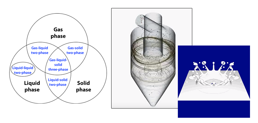
Dew condensation and evaporation can be analyzed as a type of gas-liquid two-phase flow analyses. The analysis targets are dew condensation on windows and walls inside a house and defrosters—a function to defog window glass of a vehicle.
In a dew condensation analysis, the amount of vapor in the air, i.e., humidity, is considered. For this, vapor must be treated as a variable in the fluid analysis of the gas phase. Then, dew condensation or evaporation on a wall is calculated based on the difference between the absolute humidity, which is the ratio of vapor weight to dry air weight, in the air near the wall and the absolute humidity at saturation at the wall temperature. As shown in Figure 1, when the absolute humidity in the air is greater than the absolute humidity at saturation at the wall temperature, dew condensation velocity [kg/(m2∙s)] rises and heat of 2,500 [kJ/kg] corresponding to the latent heat is generated. In an opposite case, evaporation velocity, which is the negative dew condensation velocity, increases and the heat corresponding to the latent heat is absorbed. Note that the condensed moisture, i.e., mist, is not considered even when the absolute humidity in the air exceeds the absolute humidity at saturation. In addition, the moisture condensed on the wall is assumed to be stationary, and dripping is not considered.
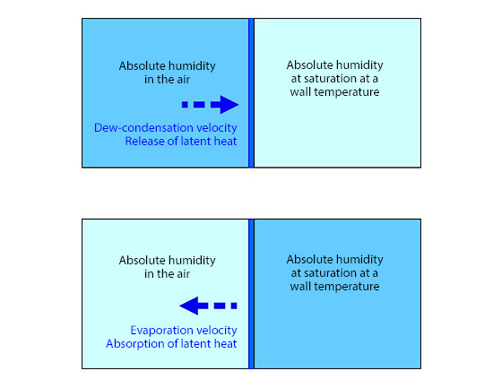
Figure 1: Dew condensation velocity
Here, let’s see an analysis example. An electric defroster, which used to be an anti-fog device on the glass of the driver’s cabin of a railroad car, is analyzed. Current railroad cars have adopted the system that defogs the entire glass of the driver’s cabin; while formerly, electric defrosters used to be installed in a part of the glass of the driver’s cabin to defog the part, as shown in Figure 2.
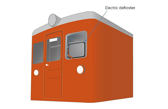
Figure 2: Railroad car
As shown in Figure 3, the computational domain is the driver’s cabin of a railroad car. The surface temperature of the driver is set to 36°C, and the amount of water generation is 9.0 x 10⁻⁶kg/(m2s) (50mL/h). The outside surface temperature of the glass of the driver’s cabin is set to -5°C, and the surface temperature of the cabin’s door is 20°C. For other boundaries, adiabatic conditions are applied. The initial temperature of the driver’s cabin is set to 20°C, and the initial humidity is 55%. Buoyancy is considered.
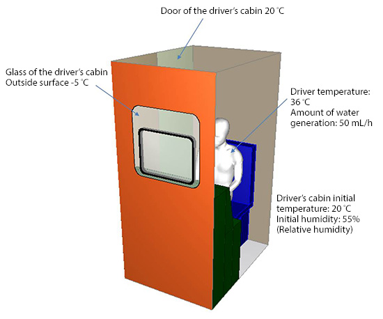
Figure 3: Driver’s cabin
Figure 4 shows the structure of an electric defroster: heating wires are surrounded by the glass of the driver’s cabin, a frame, and framed glass. That is, an electric defroster is double-glazed to keep warmed air inside. In this analysis, four heating wires are used and they start heating 90 seconds after the simulation starts. The heating rate reaches 50 W per wire in 10 seconds, and it is maintained thereafter.
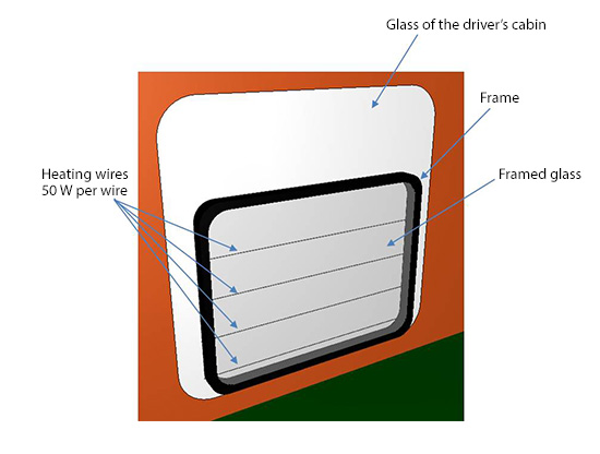
Figure 4: Electric defroster
Figure 5 shows time-series data of the surface temperature distribution on the glass of the driver’s cabin seen from the driver, while Figure 6 shows time series data of dew condensation distribution on the glass of the driver’s cabin seen from the outside. After the simulation starts, dew condensation occurs on the glass surface of the driver’s cabin for 90 seconds. Then, as heat is generated from the heating wires, dew condensation is being removed. Note that Figures 5 and 6 are animations 20 times faster than the real time.
Figure 5: Temperature distribution
Figure 6: Dew condensation distribution
The next issue will introduce another example of dew condensation simulation.

About the Author
Katsutaka Okamori | Born in October 1966, Tokyo, Japan
He attained a master’s degree in Applied Chemistry from Keio University. As a certified Grade 1 engineer (JSME certification) specializing in multi-phase flow evaluation, Okamori contributed to CFD program development while at Nippon Sanso (currently TAIYO NIPPON SANSO CORPORATION). He also has experience providing technical sales support for commercial software, and technical CFD support for product design and development groups at major manufacturing firms. Okamori now works as a sales engineer at Software Cradle.

